


News
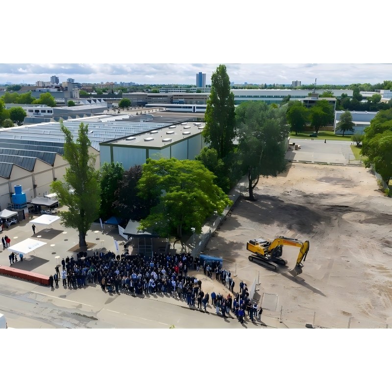
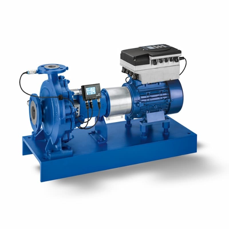
KSB launches in Frankfurt Expansion Ceremony of Eta Production Base On June 9, KSB held the groundbreaking ceremony for the expansion of its Eta production facility in Frankfurt am Main, Germany, marking another significant milestone in the company's efforts to advance high-efficiency pump manufacturing. This investment exceeds €70 million and stands as one of KSB's largest single-project investments worldwide to date. At the groundbreaking ceremony, Dr. Stephan Timmermann, CEO of KSB Group, joined Simone Schneider, State Secretary for Economic Affairs of Rhineland-Palatinate, Nicolas Meyer, Mayor of Frankenthal, and approximately 400 employees in wielding shovels to mark the beginning of a new era of production. The newly expanded Eta factory will serve as Europe's technological hub for electronically controlled pumps, integrating digitalization, energy efficiency, and smart manufacturing principles. The expansion project is scheduled for completion by 2030, involving a comprehensive upgrade of the workshop layout, optimized restructuring of machining, assembly, and logistics areas, as well as renovation of the aging production hall. By optimizing production processes, the Eta factory's annual capacity will increase from 54,000 to 65,000 pumps while maintaining KSB's consistent high-quality standards. The new facility will also feature green roofs, photovoltaic systems, and a drying system integrated with the headquarters' heating network to achieve energy efficiency. The Eta production line is now manufacturing the next-generation EtaLine Pro pumps for construction applications. Given the growing market demand for variable-frequency pumps—where such equipment accounts for 10% to 15% of Europe's electricity consumption—this upgrade not only boosts production capacity but also significantly enhances energy efficiency, delivering more sustainable solutions for customers. Since Dr. Fritz Krisam of KSB first introduced the Eta pump series in 1935/36, it has evolved into the "mother of standardized pumps" and remains a core symbol of KSB. Dr. Timmermann stated: "The Eta is not merely a product—it is the 'heart' of KSB." This expansion demonstrates KSB's strong commitment to its operations in Germany and highlights the company's ambition in technological innovation, sustainable development, and global market competitiveness. The completion of the new plant in Frankenthal will lay a solid foundation for the production of high-efficiency pumps over the coming decades.
Read More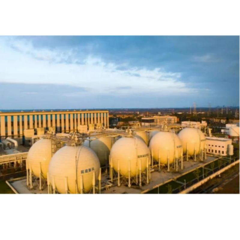
In the wave of building new power systems If we say that pumped storage is... The "big brother" in the energy storage sector So, what about large-scale, long-term physical energy storage? Compressed Air Energy Storage It's precisely that "up-and-coming technology" which has become a key pillar of the energy transition. Recently, documentaries such as "Miracle China" and "Beyond: Underground Energy Veins" have been widely broadcast on CCTV. The film features the world's first 300 MW-class compressed-air energy storage power station, hailed as a "super green power bank," which has set three world records in single-unit power capacity, energy storage scale, and conversion efficiency. It has achieved 100% domestic production of key core equipment and deep-space utilization products, making it a landmark project in China's energy transition. Behind this critical national infrastructure project, LEO Pump Industry, as the primary supplier of pump equipment, provides comprehensive solutions—including circulating pumps, makeup water pumps, and miscellaneous pumps—covering all fluid transportation requirements across power plant cooling systems, makeup water systems, and drainage systems. These efficient, intelligent, and reliable customized fluid solutions enable the successful implementation of world-class energy storage projects. project context Yingcheng in Hubei Province flourished due to its salt industry. Over 500 years ago, a heavy rain breached the rock layers of Tuanshan Mountain, transforming the area into the nationally renowned "Salt Capital and Salt Sea." As one of China's major production areas for well-mined salt, Yingcheng has developed over 40 million cubic meters of salt caverns underground—equivalent to the internal volume of 50 Fujian-class aircraft carriers! The 300 MW-level compressed air energy storage power station in Yicheng, Hubei Province utilizes underground salt caverns from abandoned salt mines as gas storage facilities. During off-peak electricity demand periods, the system drives compressors to compress and store air; during peak demand periods, high-pressure air is released to drive turbine expanders for power generation. The entire process requires no combustion of fossil fuels, achieving truly zero carbon emissions. This "air-powered battery" boasts a storage capacity of 1,500 megawatt-hours and a system conversion efficiency of approximately 70%. It can perform an energy storage cycle of 8 hours followed by a release cycle of 5 hours daily, generating about 500 million kilowatt-hours annually—equivalent to saving over 150,000 tons of standard coal—and sufficient to meet the annual electricity needs of roughly 250,000 households. Within this extensive and sophisticated system, the cooling water circulation serves as the lifeline ensuring stable operation of the compression energy storage and heat exchange systems—making LEO Pump Industry the trusted guardian of this critical infrastructure. Project Challenges For such a world-class project, the "Nengchu No.1" imposes stringent technical requirements on its high-and low-temperature cooling water circulation system. ①Extremely wide load adjustment range: Frequent switching between compression and power generation modes requires the circulation pump to operate stably and efficiently across the entire rated flow range of 50%–150%, while preventing motor overload or overheating. This poses significant challenges to both the hydraulic model and power matching of the pump. ② Specialized pump adaptation for high-temperature operating conditions: The project's heat storage and exchange system requires the delivery of high-temperature circulating water, demanding that suppliers possess advanced expertise in high-temperature heat network pumps and the capability to customize solutions for specialized process applications. ③ High-reliability customization requirements: As the world's first integrated engineering system, this equipment must operate safely over extended periods in outdoor environments with alternating temperature conditions, while being equipped with highly automated variable-frequency control and intelligent monitoring systems that seamlessly integrate with the plant's DCS network. ④ Engineering challenges posed by extremely tight delivery timelines Within just two months from signing the contract to delivery, the project required completing a full set of processes—including casting and welding of specialized materials, integration of a 10 kV high-voltage frequency conversion system, and comprehensive factory testing—putting the manufacturer's end-to-end rapid response capabilities and quality control standards to the test. LEO solution LEO is one of the leading suppliers of circulating cooling water pumps for large-scale thermal power generation units in China, holding a dominant position in the industry. For this project, leveraging nearly 70 years of technical expertise in large-scale customized pump solutions, LEO has developed a comprehensive set of high-and low-temperature circulating water pump solutions specifically tailored for "Nengchu No.1". ①Deepening of high-efficiency and energy-saving technologies: LIO has supplied the Yingsheng project with GSX and GSE series single-stage, double-suction centrifugal pumps. These products have obtained China's National Grade 1 Energy Efficiency Certification and build upon the core technological strengths recognized by the Second Prize of the National Science and Technology Progress Award. With a hydraulic efficiency exceeding 90%, they deliver 3%–5% greater energy savings compared to conventional pump models. This product series achieves a broader high-efficiency operating range through optimized flow channel design and impeller structure, enabling load regulation across 50%–150% of the rated flow rate while maintaining stable performance during transitions between compression and power generation modes. ② High-temperature resistant operation: For high-temperature operating conditions in heat storage and exchange systems, LEO has installed three DSR high-temperature circulating water pumps specifically designed for extreme thermal environments. These pumps operate at 181°C with a rated flow rate of 1,195 m³/h and a head of 45 m, powered by a 1:1 variable-frequency drive system. ③Smart Operation: LEO not only supplies the pump unit itself but also integrates a complete set of instrumentation and control systems. By configuring a 10 kV high-voltage frequency conversion device and a 380 V low-voltage frequency conversion control cabinet, intelligent stepless speed regulation for the pumps is achieved. Additionally, sensing components such as temperature-resistant thermistors and vibration probes are installed at critical locations within the pump assembly, enabling real-time comprehensive monitoring of bearing temperature, vibration, and pressure. These systems are fully integrated into the plant-wide DCS system, achieving true "unattended operation with minimal personnel required for inspection." LEO has also integrated a pump health monitoring platform into the equipment. Leveraging AI-driven data analysis, this platform provides early fault warnings, automatically generates system diagnostic reports, delivers comprehensive data support for energy efficiency optimization, and reduces operational costs by 30%. ④ Fast Delivery: To meet the stringent two-month delivery deadline, LEO Pump Industry adopted a digital collaborative manufacturing approach, successfully completing critical processes—including customized production of large dual-suction pumps and welding of special materials—with exceptional quality, thereby passing the rigorous testing required for the world's first integrated pump system project. Flow Towards The Future With the full-capacity grid connection of "Nengchu No.1," the LEO pump unit operates around the clock above the underground salt cavern, ensuring the safe and efficient operation of this "super green power bank." Since commissioning, the LEO pump unit has maintained consistently high reliability, reliably meeting the cooling and water-supply demands of the power plant's compressed energy storage system and heat storage/transfer system, thereby providing robust fluid support for achieving a 70% energy conversion efficiency in the "Energy Storage No.1" project and establishing it as a world-class benchmark in energy storage. As the core equipment supplier for the world's first 300 MW-class non-combustion compressed air energy storage power station, LEO Pump Industry has once again demonstrated its technical expertise and brand reputation in the fields of advanced energy storage and power systems. With meticulous craftsmanship and unwavering reliability, from traditional circulating pumps for thermal power plants to core auxiliary equipment for advanced energy storage systems, LEO Pump Industry has consistently focused on the efficient transportation and precise control of energy fluids. In response to the new integrated energy landscape encompassing generation, grid, load, and storage, Leo will continue to contribute its expertise through efficient and reliable smart fluid solutions, supporting the global green energy transition and China's "dual carbon" strategy.
Read More
Technology driven sustainable future This year marks the beginning of the 15th Five Year Plan, and April 22nd is the 57th World Earth Day. As global industries enter the deep waters of low-carbon transformation, sustainable development has become an important component of long-term competitiveness for enterprises. For KSB, sustainability is not just a phased goal, but a systematic action integrated into the entire process of corporate strategy, product innovation, and operational management. As a company that joined the United Nations Global Compact in 2010, KSB has always benchmarked against the 17 Sustainable Development Goals of the United Nations and built a robust and executable green development path with clear and quantifiable 2030 commitments. Drive real emissions reduction with clear goals KSB has set clear carbon reduction and management goals around climate responsibility and corporate governance. KSB Sustainable Development Goals By 2030 Environment · Compared with 2024, KSB has reduced Scope 1 and 2 greenhouse gas emissions by over 25.2%, and cut the total emissions of Scope 3 major pollutants by 15%. · The proportion of renewable energy in KSB's total electricity consumption has exceeded 80%. · KSB's annual water consumption has been reduced to approximately 966 cubic megajoules. · Compared with 2024, the greenhouse gas emissions of KSB's power supply assets in operation have dropped by 40%. Society · In group management, female employees account for no less than 15% of first-level managers, no less than 15% of second-level managers, and no less than 18% of all management positions nationwide. · The average annual training hours for KSB's frontline employees and technical personnel have exceeded 15 hours. · All business units of KSB must comply with the "KSB Supplier Code of Conduct" or equivalent standards, and all suppliers must have core business integrity training for their employees, with sustainable development training provided every three years. · The lost time injury frequency rate (LTI) per million person-hours has been kept below 3.2. · The number of employee academic qualifications above junior college has exceeded 75%. Governance · KSB conducts sustainability risk assessments for over 400 of its existing suppliers that are involved in potential sustainability risks. · All newly purchased suppliers must comply with the "KSB Supplier Code of Conduct" or equivalent standards. · All suppliers must have core business integrity training for their employees, with sustainable development training provided every three years. Based on international standards, KSB proposes the following development goals: -By 2030, the direct and indirect energy emissions generated by the company's own operations (Scope 1&2) will be reduced by more than 25.2% compared to 2024; -Reduce key value chain emissions (Scope 3) by 15%; -The proportion of renewable electricity in the total electricity consumption of enterprises has increased to over 80%; -On sale water pumps help customers achieve energy savings of no less than 26 gigawatt hours annually; -Power station pump products achieve a 40% reduction in greenhouse gas emissions during customer operation. In terms of carbon emission management, internationally, corporate emissions are usually classified into three categories: -Scope 1 (Direct Emissions): Emissions directly generated during the operation of a company, such as carbon dioxide produced by the combustion of gas boilers in factories. -Scope 2 (Indirect Energy Emissions): Emissions generated during the production process of electricity or heat purchased and used by enterprises. -Scope 3 (Value Chain Emissions): Indirect emissions from upstream and downstream of enterprises, such as emissions generated during raw material production, logistics transportation, and product use stages. Sustainable development belongs not only to the enterprise itself, but also to the entire value chain. At the governance level, KSB conducts sustainable risk assessments on over 400 existing suppliers annually and establishes a systematic supplier sustainable management mechanism From admission review, annual risk assessment to code of conduct implementation, new suppliers must comply with the company's sustainability standards; At the same time, through specialized training, we aim to enhance the purchasing team's capabilities, ensure the true implementation of sustainable concepts, and ensure that green concepts are integrated into the supply chain system. Make the fluid system a key variable for carbon reduction Data shows that the global pump system consumes approximately 20% of the total global electricity demand. Therefore, improving the efficiency of pump and valve products is an important lever for achieving large-scale carbon reduction in the industrial field. Production end: -KSB Shanghai was awarded the title of "Shanghai Green Factory"; -The Grovetown production base in the United States has achieved 100% renewable electricity supply; -The Frankenthal production base in Germany utilizes biomass boilers to achieve energy recycling; - …… Through energy structure optimization and material recycling, KSB continues to reduce its carbon footprint in the production stage. Product end: -The hydraulic efficiency of the all-new MultiTec Plus multi-stage centrifugal pump has exceeded 83%, significantly higher than industry standards; -Provide customized pump and valve solutions for clean energy projects such as biomass, wind power, photovoltaics, and green hydrogen; -Continuously promote the power station pump to achieve a 40% emission reduction target during customer operation; - …… Against the backdrop of increasing customer attention to full lifecycle costs and carbon emissions performance, efficient and energy-saving products not only reduce operating costs, but also become an important support for enterprises' green transformation. From clear emission reduction paths to efficient product innovation and supply chain collaborative management, KSB has always adhered to the concept of "Solutions. For Life", transforming sustainable development into measurable, executable, and sustainable actions. World Earth Day is only one day a year, Guarding a green future is KSB's every day.
Read More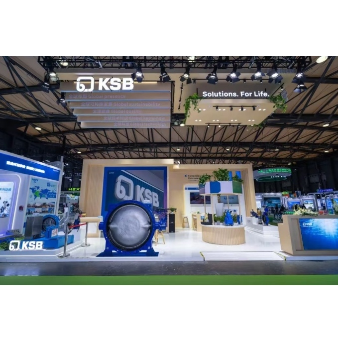
KSB leverages its digital intelligence and low-carbon hard power Leading the way towards sustainable development From April 13th to 15th, the 27th China Environmental Protection Expo, the flagship exhibition of Asian environmental protection, grandly kicked off at the Shanghai New International Expo Center. KSB showcased its pumps, valves, and next-generation digital solutions at booth B30/C29 in Hall E1, focusing on the forefront of smart environmental protection and exploring new paths for high-quality industrial development. The booth was highly popular and became the focus of industry attention. Exhibition matrix Efficient + Low Carbon + Intelligent The environmental protection industry is bidding farewell to scale expansion and moving from engineering driven to a new stage of high-quality development characterized by intelligent prevention, low-carbon recycling, and high-value resource utilization. Based on the transformation needs of the environmental protection industry in the first year of the 15th Five Year Plan, KSB focuses on the core pain points of water treatment and brings one-stop solutions for all scenarios. With the dual wheel drive of "product+technology", it demonstrates the strength of a leader in high-end fluid equipment. High performance fully covered pump set Star pump models such as stamping horizontal multi-stage pump Movibloc, vertical multi-stage pump Movitec, horizontal end suction pump Etablac and MegaCPK, axial split volute centrifugal pump Omega, submersible centrifugal pump Amarex KRT, and KSB original mechanical seal spare parts were showcased, covering all scenarios such as sewage treatment and industrial circulation, with high efficiency, stability, low consumption, and long service life, laying a solid foundation for the core equipment of water treatment systems. Flagship valve lineup The large-diameter butterfly valve MAMMOUTH is once again unveiled: as a practice of KSB's localization strategy in China, it not only fills the technological gap in the field of high-end fluid equipment in China, but also demonstrates the resilience of "Made in China" in the global industrial chain. The DUALIS-C hydraulic butterfly valve, ECOLINE gate valve, HERA-BDS knife gate valve, BOAX-B butterfly valve and other products exhibited this time have the characteristics of low energy consumption and high energy efficiency, making them the best choice to help achieve the dual carbon goal. Additionally, it is worth mentioning that KSB has brought the ISORIA rubber coated butterfly valve optimized specifically for seawater desalination scenarios. With high reliability, it helps emerging low-carbon application scenarios and further improves the overall layout of water equipment. Digitized solutions KSB believes that the future development of the environmental protection industry depends not only on visible equipment, but also on invisible efficiency, energy consumption, and risk management. KSB is committed to becoming a long-term partner for customers in core value areas such as smart operations, green energy and carbon, and intelligent diagnostics. At this year's Environmental Expo, two major digital core achievements of KSB China, Kaipum Guard and KSB Smart Factory, were showcased on site: relying on the Internet of Things, algorithms, big data, and digital twin technology, Kaipum Guard achieved predictive maintenance of rotating products, giving every device the ability to "predict". KSB Smart Factory connects the entire production, planning, and maintenance chain, empowering green and sustainable development with refined energy management, visualizing and controlling the entire area, and building a safe and smart park. Under the dual carbon background KSB Solution During the exhibition, KSB deeply participated in high-end industry exchanges, empowering industrial transformation with professional strength and conveying the concept of sustainable development. On April 13th, Cai Ying, Business Development Manager of KSB Shanghai, was invited to attend the E20 Environmental Platform Forum. With the theme of "Efficient and Reliable Application of Pumps in Industrial Water Treatment under the Background of Dual Carbon", she systematically shared how KSB helps the industrial water treatment field achieve energy conservation, consumption reduction, safety and stability, and low-carbon transformation through efficient and energy-saving pump sets and digital operation and maintenance solutions, providing a practical path that can be implemented and replicated for the industry, and was widely recognized by the guests on site. During the same period, KSB accepted an interview with the "Environmental Circle" media. Zhu Yixin, Sales Director of KSB Valve's China Water and Sewage/Export Business, and Huang Chuanxiong, Chief Expert and General Industrial and Building Industry Application Manager of KSB, combined with industry development trends, stated that "the current environmental protection market is returning to rationality, and the core competitiveness of enterprises lies in deep technological cultivation, reliable products, professional services, and full cycle value creation. KSB has always integrated low-carbon concepts into the entire process of research and development, design, production, and service, relying on digital technology to continuously explore energy-saving potential, providing customers with globally leading fluid solutions, and helping the industry achieve green transformation. For over 150 years, KSB has adhered to a long-term philosophy, always practicing the concept of sustainable development, using technological innovation as the engine, and continuously cultivating the environmental protection and water market. Based on the beginning of the 15th Five Year Plan, the current environmental protection industry has entered an era driven by technology and value. KSB China has been practicing the "double carbon" strategy, deeply integrating German Seiko with local innovation, and promoting the pump valve equipment to be intelligent, low-carbon and integrated. In the future, we will continue to adhere to the solution The brand concept of achieving a better life, with more reliable products, smarter solutions, and more professional services, collaborates with global partners, links global green opportunities, and jointly builds a low-carbon, efficient, and intelligent new ecological environment for environmental protection.
Read More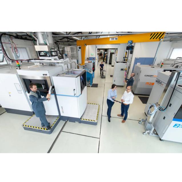
KSB Additive Manufacturing Technology In the industrial manufacturing sector, a technology that revolutionizes traditional cutting processes is reshaping the future—additive manufacturing (commonly known as 3D printing). Unlike traditional processes that perform "subtractive" cutting on metal blanks, additive manufacturing achieves "additive" shaping by layer-by-layer stacking of powder materials. As a global pioneer in this field, KSB is leveraging this transformative technology to address extremely complex engineering challenges for clients through its forward-looking strategic deployment. Over two decades of dedicated expertise Secured the world's first TUV certification KSB's leadership in the field of additive manufacturing did not come overnight. As early as 2003, when "3D printing" had not yet gained widespread industry attention, KSB's innovation team had already initiated comprehensive technical evaluations and prototype development. This predates the inclusion of additive manufacturing in the Gartner Technology Maturity Curve by five years. Today, this first-mover advantage has borne abundant fruit: KSB has become the world's first manufacturer to obtain TUV certification for additive manufacturing components in compliance with the EU Pressure Equipment Directive. This achievement represents not only an industry milestone but also the highest recognition of KSB's products' exceptional safety and reliability. Breaking geometric limits Empowering Small-batch and Complex Customization Complex geometric shapes that are difficult to achieve through traditional casting or machining can be effortlessly resolved with additive manufacturing. KSB currently utilizes various metals, plastics, and composite materials for 3D printing. ● Shorten delivery cycles: Rapidly respond to urgent replacements of non-standard components. ● High-efficiency customization: Capable of efficiently producing single items and small-batch special-design products. ● Performance leap: Novel components specifically developed for this process, delivering superior hydraulic and structural performance. Classic example: One-piece molded pump housing with integrated heating channels When handling temperature-sensitive media such as vegetable oil and caustic soda, pump housings must maintain constant temperature. In the past, engineers had to rely on extremely complex welding procedures to secure heating channels on the exterior of pump casings. Now, KSB experts utilize additive manufacturing technology to seamlessly integrate heating channels directly into pump casings through "one-piece molding." This innovation eliminates cumbersome post-processing steps, significantly extending component durability and enhancing thermal conductivity efficiency. Pegnitz, Germany KSB Full Function Additive Manufacturing Center Currently, the additive manufacturing center of Kaisi located in Pegnitz, Germany is equipped with industry-leading manufacturing equipment. We are not merely "printing" products but also providing customers with one-stop services covering the entire industrial chain: ● Professional equipment consultation and process evaluation ● Component Design and Topological Optimization Renovation ● High-standard actual production and processing ● Rigorous material and quality control system
Read More
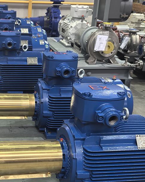
KSB, a global leader in pump and valve solutions, has achieved another milestone by securing a major order worth over €150 million, setting a new single transaction record since the company's inception. This order originates from a nuclear power plant in Eastern Europe, with KSB's energy division supplying eight reactor primary coolant pumps. Each pump weighs over 100 tons and has a rated power output of 8 megawatts, to be manufactured at KSB's headquarters facility in Frankenfurt, Germany. The contract encompasses not only core equipment supply but also comprehensive testing services, marking the largest single order in KSB's development history. As the "heart component" of a nuclear power plant, the main coolant pump is responsible for driving the coolant circulation and diverting fission thermal energy. This project will strongly support Europe's clean energy transition, enhancing energy security and independence. Through technological innovation and deep industry expertise, KSB is steadily consolidating its leadership in the global power plant pump market while advancing a clear growth strategy.
Read More
Four-time consecutive championship! Wilo is honored as a global 'Successful Practice Enterprise' again, with its innovation capability certified by international authorities In the 2025 Consortium Benchmarking Study, a collaborative initiative by RWTH Aachen University and global industry leaders, Wilo Group has once again distinguished itself among numerous enterprises worldwide, securing the prestigious title of 'Successful Practice Company' for the fourth consecutive year. Since 2022, wilo has maintained this certification for four consecutive years, establishing industry benchmarks in digital product development (2022), sustainable development (2023), and artificial intelligence (AI) (2024). This year, the research, themed 'Driving Innovation: The Key to Global Competitive Success,' once again highlights wilo's success in making innovation its core strategy. Gathering of Elite, Discussing the Way of Innovation A standout feature of this study was the gathering of five selected 'successful practice enterprises' at Wilopark in Dortmund, Germany, for an in-depth exchange on successful innovation methodologies. Partners including Siemens, Endress+Hauser, and Vaillant were also present, jointly exploring how to forge and sustain robust innovation capabilities in global competition. Innovation is not the goal but the responsibility At the event's opening, Mr.Georg Weber, Global Chief Technology Officer (CTO) of Wilo Group, delivered a keynote speech. He stressed:' For us, innovation is not an end goal but the cornerstone of sustainable competitiveness. In today's globalized world, technological excellence, digitalization, and the responsible use of artificial intelligence must advance in tandem. Our vision is to develop innovations that create real added value and always put people at the centre – whether our customers, society or future generations. ——Georg Weber Member of the Executive Board and Chief Technology Officer of Wilo Group 150 Years of Unchanged Commitment, AI Empowers Water Future This human-centered commitment stems from Wilo's 150-year legacy. For over a century, Wilo has been committed to improving global living standards through its products and solutions, ensuring access to clean water. Today, this commitment is being revitalized through cutting-edge technology. A prime example is the newly launched "Wilo Global Water AI Academy" by wilo, which aims to deeply integrate water resource management, advanced science, and artificial intelligence to cultivate future-ready professionals and drive intelligent transformation in the water industry. From concept to practice, Wilo's innovative panorama During the subsequent panel discussions, attendees gained in-depth insights into Wilo's end-to-end innovation ecosystem, covering its efficient management framework, proven best practices, and rigorous IP strategy. The event culminated with a factory tour at Wilo's campus, where guests witnessed firsthand how these innovative concepts are translated into tangible productivity. Innovation is the key to open the door to the future Wilo Group's commitment to innovation is never a one-off short-term initiative, but rather a strategic investment that shapes long-term competitiveness, corporate resilience, and sustainable growth. It also forms a core component of the company's social responsibility. As this research phase concludes in March 2026, wilo will remain steadfast on its innovation journey—working with powerful partners to transform innovation, the key success factor, into a powerful force driving progress in the global water sector, guided by a clear vision for the future.
Read More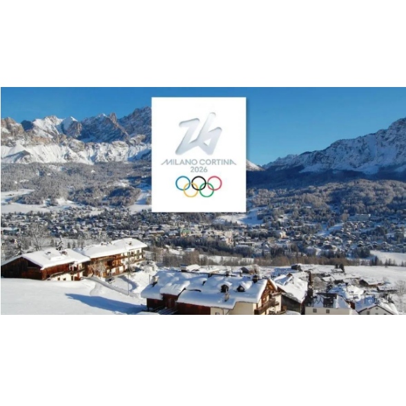
Dreaming of ice and snow! Wilo pump solutions power sustainable momentum for the 2026 Milan-Cortina Winter Olympics The 2026 Winter Olympics in Cortina d 'Ampezzo, Italy, was successfully held from February 6 to 22. This marked the third time Italy hosted the Winter Olympics and the first time Cortina d' Ampezzo had hosted the event in 70 years. The Winter Olympics adopted a historic 'decentralized hosting' model, with events spread across four major regions: Milan, Valtellina, Cortina, and the Fiume Valley. Covering over 22,000 square kilometers in northern Italy, the Games saw participation from approximately 2,900 athletes representing 93 delegations. In the end, Norway topped the gold medal table with 18 golds, 12 silvers, and 11 bronzes, while the host country Italy ranked fourth with 10 golds, 6 silvers, and 14 bronzes, achieving its best performance since 1994; the China delegation set a new record for its best overseas performance with 5 golds, 4 silvers, and 6 bronzes! How could such a grand sports event with multiple venues be without the water system's' powerful heart'—the pumps? As highlighted in multiple reports from the 2022 Beijing Winter Olympics, Wilo Pumps delivered efficient, reliable, and customized pump solutions for critical infrastructure including ice-making and heat recovery systems in ice venues, snow-making water supply systems in snow venues, and cloud data centers supporting event operations. This showcased the company's commitment to' German quality with energy efficiency' in top-tier sporting events. At the Milan-Cortina Winter Olympics, Wilo partnered with ISP, an industrial solutions provider, to deliver multiple pump module sets featuring the Wilo-Atmos GIGA-I product. These high-efficiency pump systems played a pivotal role behind the scenes, providing robust support for the Olympic infrastructure. You've probably noticed—where's that familiar shade of 'Weilu Green' gone? This product line was specially customized to meet the client's requirements, with all' Weilu Green' units replaced by blue paint. Rest assured, despite the new blue exterior, they remain 100% Weilu quality. The core values of German craftsmanship, energy efficiency, and digital innovation remain unchanged! For Wilo, this is not merely a product delivery, but a declaration. The 2026 Milan-Cortina Winter Olympics consistently emphasizes energy efficiency, adaptive reuse, and eco-friendly solutions. Wilo's technology is contributing to the creation of this sustainable Olympic vision!
Read More
Wilo Global ▏ Wilo Group launches the global WATER AI Academy, effectively bridging water resources and AI expertise On January 30,2026, in Dortmund, Germany, the Wilo Group officially announced the establishment of the Global WATER AI Academy at its headquarters, Wilopark. Through this initiative, the water technology group will connect global science and industry, promote applied science and innovation, and foster collaboration in the fields of water and artificial intelligence across industries and national borders. The first partnership of the newly established institution targets students and experts: in collaboration with the internationally renowned Heriot-Watt University, Wilo Global WATER AI Academy is developing an educational program that will receive accreditation from the international higher education system. The establishment of Wilo Group's global WATER AI Academy has consistently aligned with our sustainable development strategy. ——Oliver Hermes President and CEO of Wilo Group Wilo is enhancing the quality of life for people worldwide by systematically integrating water technology with artificial intelligence. This methodology is embodied in guiding WATER AI principles, representing Wilo's response to the AI era. We emphasize three Es: Enable (empowerment), Embed (integration), and Embrace (AI adoption). By embedding AI into our products and solutions, Wilo has created lasting positive market impact. This approach also unlocks the entire AI value chain. Naturally, Wilo actively embraces AI in its daily operations. Wilo's sustainable development and AI-integrated solutions drive smart water conservation in cities. Moreover, access to clean water will be better managed and enhanced through intelligent systems. Food security is also improving, exemplified by digital solutions for agricultural irrigation. Healthcare will also benefit from WATER AI. The digital and AI era fundamentally relies on smart water technologies, and Wilo's strategic principles align with WATER AI's vision: Only by organically integrating water and AI can we achieve a sustainable future. ——Oliver Hermes President and CEO of Wilo Group Heriot-Watt University (HWU), a public institution headquartered in Edinburgh, Scotland, operates international campuses in Dubai and Malaysia. It was the first foreign university to establish a campus in Dubai over two decades ago. HWU Dubai has maintained a successful partnership with Wilo Group for several years, and their first jointly designed online course is currently under joint development. "We are delighted to establish this partnership with the Wilo Group. Water and artificial intelligence are two pillars of global progress, both representing internationally recognized expertise at Heriot-Watt University. Our online learning modules set new benchmarks for digital education. Each course module is meticulously designed to combine academic rigor with intuitive, user-friendly experiences, ensuring learners benefit from meaningful and impactful content in an engaging way," commented Professor Lynne Jack, Vice-Chancellor of Heriot-Watt University Dubai. Through the groundbreaking WATER AI Academy, we champion AI and partnerships with a human-centric approach. Wilo is integrating the planet's most vital resources with this transformative technology. ——Oliver Hermes President and CEO of Wilo Group With its exceptional teaching content and services, the college aims to attract a diverse range of students, trainees, career beginners, and seasoned professionals from both within and beyond Wilo. Although currently managed by Wilo Group's Dortmund headquarters, the college is clearly striving to build a globally connected community of knowledge and innovation. The expanding partner network will undoubtedly benefit all stakeholders.
Read More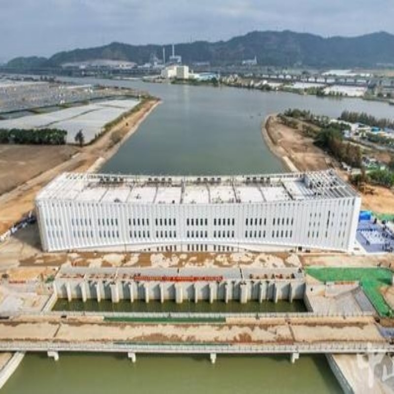
Asia's largest single pump station officially opened On January 20, the launch ceremony of the first batch of key projects for the "15th Five-Year Plan" of Beautiful and Happy Rivers and Lakes in Zhongshan City and the water supply ceremony for key water conservancy projects during the "14th Five-Year Plan" were held at the Xihé Water Conservancy Hub Project site in Banfu Town. On that day, 11 key projects for Beautiful and Happy Rivers and Lakes, with a total investment of nearly 20 billion yuan, were officially launched. The Xihé Pump Station, designed with a drainage flow rate of 400 cubic meters per second and the largest single-unit flow rate in Asia, was officially put into operation. Guo Wenhai, Secretary of the Zhongshan Municipal Party Committee, announced the launch of the key projects for Beautiful and Happy Rivers and Lakes and the water supply of water conservancy projects. Guo Tianguo, Deputy Editor-in-Chief of China Water Conservancy News, attended the event, and Chen Renzhu, Deputy Director of the Provincial Water Resources Department, delivered a speech. It is reported that the Xihe Pumping Station is currently the largest single-unit pumping station in Asia. Zhongshan now boasts two such stations—the Xihe and Donghe Pumping Stations—both ranking among the top five in Asia in terms of single-unit capacity. To address urban flooding in southern towns and districts, Zhongshan is actively constructing the Dayongkou Pumping Station, which will also achieve the fifth-largest single-unit capacity in Asia. The upgrading of these critical water conservancy projects reflects a city's comprehensive efforts to enhance water security resilience. On the same day, the first batch of key projects under Zhongshan City's "15th Five-Year Plan" for Beautiful and Happy Rivers and Lakes was fully launched, with 11 major projects and a total investment of nearly 20 billion yuan commencing construction. From this point of view, Zhongshan has shifted from the traditional flood control and drainage to the construction of a modern water network system integrating safety, resilience, ecology and economy. With a total investment of approximately 760 million yuan, the Xihe Pump Station, classified as a Class I large-scale (Type 1) project, demonstrates its robust capabilities through its massive scale. It features eight giant vertical shaft cross-flow pump units, with a designed drainage flow rate of 400 cubic meters per second and an emergency reverse water supply flow rate of 145 cubic meters per second, achieving a total installed capacity of 18,400 kW. This means that under extreme weather conditions and when external rivers flood, it forcefully discharges the internal floodwaters with tremendous force to counteract the tidal uplift at the Pearl River Estuary. Its flood (tide) prevention standard is designed for a 200-year return period, ensuring urban safety. The Xihé Pumping Station is located on the western embankment of Zhongshun Dawei, serving as a protective barrier for the Qijiang River internally and facing the Modaomen waterway externally, effectively addressing a critical weakness in this "life-saving defense line." Zhongshun Dawei, one of the ten major embankments in Guangdong Province, spans across Zhongshan and Shunde, safeguarding the security of 659 square kilometers of land and millions of residents. The completion of the Xihe Pumping Station now forms the Xihe Water Conservancy Hub, Zhongshan's largest water management complex, alongside the existing Xihe Water Gate and Ship Lock. This project significantly enhances the flood control and disaster mitigation system in Zhongshun Dawei, dramatically improving drainage efficiency, flood prevention, and agricultural water supply security. It effectively alleviates urban flooding pressure, strengthens drainage capacity across the Qijiang River Basin, and ensures water safety for both industrial and agricultural operations within the protected area.
Read More
Global Pump Industry Technology Development in 2025 In 2025, the pump industry is transitioning from isolated technological breakthroughs to comprehensive system integration. In 2025, the global pump industry is entering a pivotal phase of technological integration and market restructuring, driven by the dual objectives of carbon peaking and carbon neutrality, alongside the accelerated advancement of Industry 4.0. According to the annual report of the International Fluid Machinery Association, the global centrifugal pump market has reached $65 billion, with a year-on-year growth of 7.2%. Among them, the China market contributed 25% of the share, and the high-end market share increased by 6 percentage points. 1. Macro Drivers of Technological Innovation The pump industry's technological innovation in 2025 is being strongly propelled by multiple macro factors. The ongoing progress of the' dual carbon 'goals and the deep integration with Industry 4.0 jointly form the core driving force for the sector's development. Policy frameworks are driving transformative changes: The EU has implemented the MEI amendment under Regulation 547/2012, while the U.S. Department of Energy maintains stringent energy efficiency thresholds for industrial pumps. These mandatory standards are reshaping the competitive landscape of the global pump industry. In terms of technological advancement, the convergence of artificial intelligence (AI), the Internet of Things (IoT), and materials science is continuously expanding the intelligent boundaries of pump equipment. AI-driven systems can provide early warnings for potential failure risks such as impeller wear and shaft seal leakage, significantly reducing equipment failure rates. The global pump market demonstrated robust performance, with the Asia-Pacific region standing out notably. The regional market size reached $17.7 billion in 2024 and is projected to grow from $18.6 billion in 2025 to $30 billion by 2034, at a compound annual growth rate (CAGR) of approximately 5.4%. 2. Advances and Breakthroughs in Core Technologies In 2025, the pump industry is transitioning from isolated technological breakthroughs to comprehensive system integration, with four core technologies now achieving large-scale implementation. In the application of new materials, the large-scale adoption rate of silicon carbide (SiC)-reinforced impellers and corrosion-resistant alloy pump shafts has reached 68%. Silicon carbide (SiC) impellers demonstrate significant advantages in harsh industrial environments due to their excellent comprehensive performance, specifically manifested in: 1) Exceptional corrosion resistance: Capable of withstanding strong acids, strong alkalis, and oxidizing media, with performance far surpassing traditional metal materials like stainless steel. 2) Exceptional wear resistance: With a hardness comparable to diamond (Mohs hardness 9.5), it is ideal for high-wear applications like pulp conveyance, offering a service life 5-10 times longer than metal impellers. 3) Exceptional high-temperature stability: Maintains mechanical properties below 1600°C, making it suitable for high-temperature fluid transportation. 4) Lightweight design: With a density of approximately 3.1 g/cm³, it is lighter than metal, reducing the inertia of rotating components and enhancing system energy efficiency. 5) Low thermal expansion coefficient: Excellent thermal shock resistance, suitable for environments with rapid temperature changes. 6) Structural innovation enhances reliability: Novel designs such as modular splicing and internal cavities improve the impact resistance and manufacturing yield of large impellers; certain patented technologies employ metal inserts to strengthen connection integrity, effectively mitigating the risk of ceramic-metal interface failure. In the field of wear-resistant materials, the WC20Cr3C27Ni coating fabricated using HVOF and APS processes can enhance the substrate's slurry erosion resistance by 3.5 times. Digitalization and intelligentization have emerged as key innovation drivers. The adoption rate of AI-powered O&M systems has increased by 40% year-on-year, with leading brands now widely implementing features like fault prediction and energy efficiency monitoring. Modular and customized design has become crucial for addressing complex demands. For instance, Swiss company Wandfluh leverages an AI-assisted design platform to reduce the shortest delivery time for customized services to just 4 days. Breakthroughs continue to be made in extreme condition adaptation technologies, with representative products now achieving stable operation across a wide temperature range from-60°C to 500°C. 3. Technical Path and Application Analysis Table: Key Technological Pathways in Pump Industry for 2025 and Their Applications and Commercial Impacts Technical Path Core Technological Breakthroughs Typical Application Scenarios Commercial Value & Market Impact High-efficiency Energy-saving Technology Carbonization Rotor Municipal Sewage Treatment, Seawater Desalination Significantly reduces maintenance and energy costs Intelligent Operation & Maintenance HT-AI Platform (predictive maintenance accuracy: 99%), Digital Twin Technology Large-scale Power Plants, Nuclear Power Plant Cooling Systems Greatly reduces planned downtime losses Extreme Customization Wide-temperature Adaptability Technology (covers -60°C to 500°C) Deep-sea Oil & Gas Drilling, Natural Gas Transportation High-end customized orders grow rapidly; customer satisfaction rises Corrosion & Wear Resistance Technology PTFE Multilayer Composite Coating (corrosion resistance increased by 50%), Superhard WC Coating Chemical Process Treatment, Mine & Metallurgy Transportation Significantly improves market share in harsh working environments Energy-efficient technologies: By utilizing advanced materials and innovative designs, industry products now achieve 18% higher average operational efficiency and 28% lower energy consumption per unit compared to 2024 levels. A prime example is the high-efficiency wear-resistant horizontal double-suction multi-stage centrifugal pump developed by Shanghai Liancheng Group, which has been included in the "2025 Key Promotion and Guidance Catalog for Advanced and Practical Water Conservancy Technologies". This breakthrough effectively meets the stringent requirements of large-scale water conservancy projects for both high efficiency and reliability. Intelligent O&M Technology: Its core value lies in enabling predictive maintenance and remote monitoring. Solution providers like Skoda are dedicated to offering comprehensive smart equipment monitoring and predictive maintenance services for industrial enterprises, specifically manifested in: 1) Fault prediction: On average, it can forecast equipment failures 14 days in advance, providing ample preparation time for maintenance. 2) Reliable operation: The fault detection accuracy reaches 99.7%, effectively reducing false alarm and missed detection rates. 3) Cost reduction and efficiency improvement: Reduces average unplanned downtime by 35% and maintenance costs by 43% for clients. 4) Predictive maintenance: By leveraging real-time monitoring and AI analytics, it proactively detects equipment failures to minimize downtime. 5) Intelligent Diagnosis: Rapid fault detection and localization significantly improve maintenance efficiency. Customized extreme-condition technology demonstrates unique value in specialized applications. For instance, the micro ultra-pure centrifugal pump developed by German company Knoll features a compact design with a mere 0.8-liter volume and 1.2kg weight, delivering flow accuracy of ±0.5%. Specifically engineered for ultra-pure medium transportation in 18-inch wafer manufacturing, this innovation signifies a technological leap from conventional manufacturing to precision instrumentation standards. Corrosion and Wear Resistance Technology: Continuous innovation to meet the demands of special medium processing. In 2025, Germany's ProMinent introduced a new-generation hydraulic diaphragm metering pump featuring a patented PTFE multi-layer composite diaphragm, which offers 40% enhanced corrosion resistance compared to the previous generation and is compatible with highly corrosive media ranging from pH 0 to 14. In the slurry treatment sector, researchers have significantly improved the service life of materials in solid particle-containing media through thermal spraying technology. 4. Industry Applications and Market Reactions In 2025, diverse application fields will drive differentiated demands for pump technologies, fostering diversified technological development. In the water and wastewater treatment sector, the growth in global water treatment expenditures has emerged as a key driver, with municipal and industrial water operators accounting for 28.2% of the total revenue in the industrial pump market. The U.S. Environmental Protection Agency (EPA) estimates that long-term remediation needs in this field exceed $744 billion, further accelerating the multi-phase upgrade process. The petrochemical and chemical industries impose exceptionally stringent requirements on pump technology. In large-scale cracking units, single-stage cantilever pumps are typically employed for lighter hydrocarbon media, while multi-stage radial split pumps are utilized for high-head reformate recycle operations. ProMent, a German manufacturer, has delivered 800 corrosion-resistant pumps to global chemical giants including BASF and Bayer, and has secured 12,000 new clients in high-corrosion environments. The rapid development of the new energy industry has spurred demand for advanced pump technologies. Emerging sectors such as lithium batteries and nuclear power have seen annual demand growth exceeding 20%, serving as the core growth drivers for the industry. The hydrogen energy sector has created a new frontier for pump technology. Green hydrogen projects require multi-stage booster pumps made of AISI 316 stainless steel and certified with ATEX regional safety. The pump industry is now facing a critical transition from traditional fluid transportation to advanced energy medium processing. 5. Regional Development Patterns and Differentiated Competition In 2025, the global pump market will feature a diversified regional competition landscape, with each major region developing distinct strategies based on its unique strengths. The Asia-Pacific region, especially the China market, has become the core engine of growth for the global pump industry. The scale of China's centrifugal pump market has maintained a growth rate of over 8% for seven consecutive years and is expected to exceed 15 billion yuan by 2025. Chinese pump manufacturers are achieving a strategic transformation from "technological follower" to "comprehensive leader," with the market share of domestic products rising sharply from 60% a decade ago to 92%, and the self-reliance rate of core technologies exceeding 96%. European enterprises continue to maintain global leadership in precision manufacturing and high-end customization. For instance, Germany's Kono holds a 65% market share in the semiconductor-specific pump sector. European industrial clusters contribute approximately 32% of global pump market revenue, dominating the high-end precision segment. The North American market primarily targets industrial high-volume applications. Confronted with competitive pressures from low-cost manufacturing regions, North American suppliers are actively strengthening their market position through technological innovation and digital transformation. 6. Future Trends and Challenges in Technology Looking ahead to 2026 and beyond, the global pump industry is expected to evolve along three key directions while facing a range of challenges. The trend of technological convergence is intensifying. Future pump technologies will demonstrate deeper integration of electromechanical-hydraulic systems and cross-domain fusion. The combination of artificial intelligence, IoT technologies, and fluid dynamics will give rise to smarter, adaptive pump systems. Taking the hydraulic pump sector as an example, the development of electro-hydraulic units is steering toward more integrated and comprehensive electrification solutions. Sustainable development demands upgrades. Driven by increasingly stringent environmental regulations, pump remanufacturing and material recycling will become key industry trends. The EU's Circular Economy Directive is boosting revenue growth in related remanufacturing businesses and increasing market demand for pump products that comply with EN ISO 14971 standards and possess eco-design characteristics. Emerging application fields are continuously expanding. Emerging sectors such as hydrogen energy infrastructure, carbon capture, utilization and storage (CCUS), and advanced energy storage systems are providing a new stage for pump technology. For instance, the Star Pump Alliance has demonstrated a sealed high-pressure pump solution specifically designed for hydrogen production, where this early-stage niche market imposes extremely high requirements on material corrosion resistance and zero-leakage performance. The challenges facing the industry are becoming increasingly prominent. The sector is simultaneously confronted with multiple challenges, including fluctuations in raw material prices, restructuring of global supply chains, fragmentation of technical standards, and cybersecurity risks. Particularly with the widespread adoption of intelligent pump systems, cybersecurity has emerged as a severe issue that cannot be overlooked.
Read More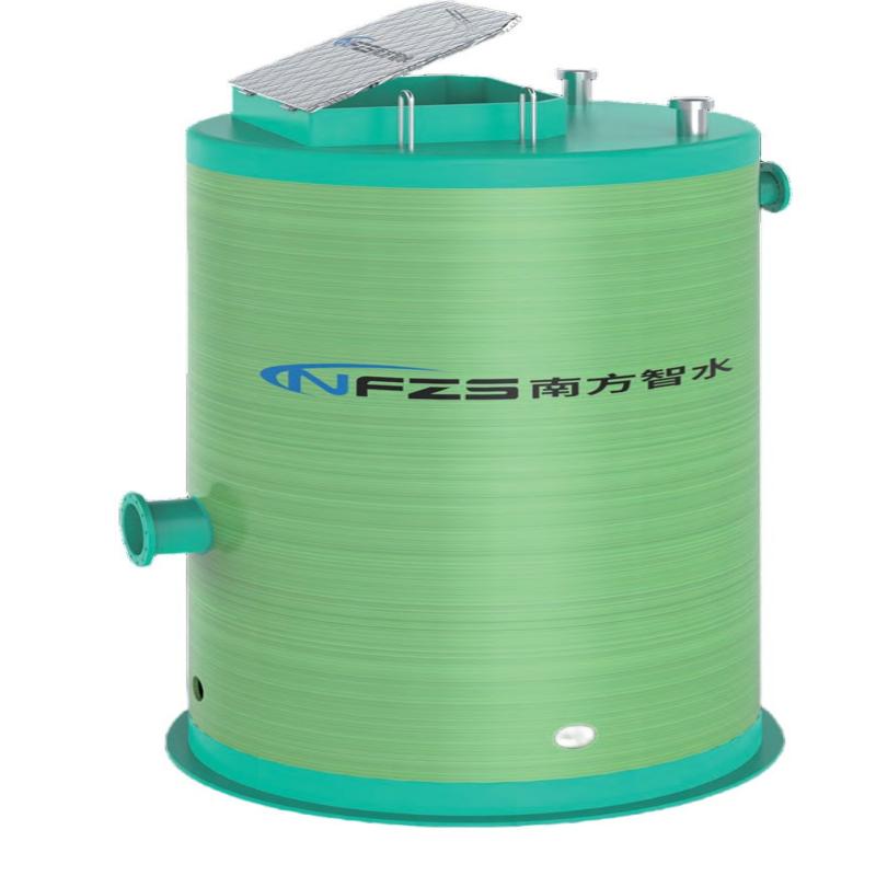
Nanfang Pump Industry-China Energy-saving Pump King Deep within the urban fabric and rural development networks, a quiet revolution in water resource management is unfolding. Traditional infrastructure's cumbersome inefficiency is being progressively replaced by intelligent, integrated prefabricated pumping stations. These structures are far from mere cold concrete buildings—they function as "urban organs" imbued with vitality, ready to operate upon arrival at project sites, providing continuous energy for the city's "circulatory system." In this issue, we highlight exemplary cases from diverse regions that confront multifaceted challenges, revealing how these 'underground guardians' —with their profound wisdom and steadfast resolve—are redefining humanity's relationship with water. Case 1: Building the "Intelligent Hub" of Water City in Eastern Hubei Huanggang Integrated Prefabricated Pump Station Case The project's core focus lies in "precision" and "reliability". Confronting complex geological conditions and a tight construction window, the team successfully overcame challenges in maintaining stable operation of the pumping station under high-head and high-flow conditions, achieving seamless integration with the aging pipeline network with zero leakage. The built-in intelligent control system functions as an "autonomous decision-making hub", providing remote monitoring, smart start-stop control, and fault alerts to strengthen drainage safety during extreme weather. This project marks a critical leap from "spot treatment" to "system-wide governance". It not only effectively safeguards urban lifelines but also significantly enhances Huanggang's disaster resilience as a key city in eastern Hubei. The smart water management practice featuring "distributed layout and comprehensive coordination" offers a "Huanggang Solution" with both practical applicability and reference value for modernizing drainage systems in similar urban clusters. Case 2: The Hometown of Xi Shi Adds "Smart Water Manager" Zhuji Integrated Prefabricated Pump Station Case The project's core challenge centers on "precision integration." It requires not only millimeter-level installation of the pumping station on soft soil to ensure seamless integration with complex existing pipelines, but also harnesses intelligent sensing and control systems to transform the station into an experienced "water management expert." By autonomously optimizing operational strategies based on real-time water data, it ensures drainage efficiency while achieving precise balance between energy consumption and environmental impact, enabling eco-friendly operation. The completion of this pumping station vividly demonstrates the "Lucid waters and lush mountains are invaluable assets" concept in municipal engineering. Its successful application provides a replicable and scalable "Zhujie model" for drainage system construction in densely water-networked and ecologically sensitive regions of nanfang China. Case 3: Resilience Cornerstone in the Ice City's Pulse Case of Shenyang Integrated Prefabricated Pump Station The project's core breakthrough centers on "intelligent cold-resistant control," overcoming technical barriers to ensure stable equipment operation in extreme cold environments. Through innovative applications of specialized composite materials and customized electric heating systems, it guarantees continuous high-power output from pumping stations during harsh winter conditions. The integrated intelligent control system functions like an "autonomic nervous system," dynamically adjusting operational status in real-time to respond to environmental changes. This enables proactive ice formation risk warnings and adaptive protection, thereby establishing a robust safety barrier for drainage systems in cold regions. The completion of this pumping station marks a paradigm shift in municipal infrastructure development in northern cold regions. It not only serves as a vivid demonstration of 'new quality productivity' in the municipal sector, but also highlights the enhanced disaster resilience and modern governance capabilities of Shenyang. Case 4: Modern Protection of Ancient Capital Water Vein Case of Xi'an Integrated Prefabricated Pump Station The project's core challenge centers on achieving "harmony between past and present." During construction, micro-disruption techniques were employed to precisely install the pumping station while fully preserving the surrounding historical strata. The intelligent control system integrates big data analytics to develop predictive dispatch capabilities, ensuring rapid response to sudden heavy rainfall while achieving seamless coordination with the city's existing drainage network for comprehensive, efficient urban management. The establishment of this pumping station represents not only an iterative upgrade of urban infrastructure, but also a profound tribute to historical heritage by modern urban civilization. The project successfully achieves a dual focus on 'preservation' and 'enhancement,' allowing the ancient waterways of this millennium-old capital to continue nourishing urban development and perpetuating the roots of civilization for contemporary times. Case 5: Green Empowerment of Industrial City Zibo Integrated Prefabricated Pumping Station Case The project's core highlights demonstrate a "balance of rigidity and flexibility." The integrated intelligent monitoring platform achieves data linkage with the regional environmental protection system, transforming the pumping station into a "frontline sentinel" for urban water environment management. While reinforcing the safety barrier of drainage systems, it provides precise data empowerment for environmental supervision. The construction of this project has transcended the single-function scope of traditional municipal engineering, serving as a vivid testament to Zibo's green transformation as an industrial city. It not only significantly enhances the city's flood control and drainage capabilities but also promotes continuous improvement in regional water environment quality through end-to-end intelligent management. From the nanfang water towns to the northern frigid regions, from historic cities to industrial hubs, these integrated prefabricated pumping stations—deeply embedded in diverse urban landscapes—demonstrate through their exceptional adaptability and foresight that true infrastructure wisdom lies not in grand engineering feats, but in precise alignment with regional characteristics and profound integration of human-centric warmth. More than mere technological carriers, they silently embody urban ideals—operating with resilient and intelligent rhythms in underground spaces to safeguard every city's tranquility, cleanliness, and vitality. In the future, this product will take root in more soils, enabling deeper harmonious coexistence between cities and nature through the cyclical flow of water.
Read More


 IPv6 network supported.