


fter-sales
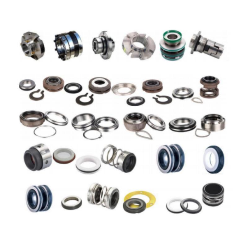
Industrial sealing materials with varying hardness levels Sealing materials are a critical industrial material used to prevent the leakage of gases, liquids, or other substances, widely applied in various fields such as construction, automotive, aerospace, electronics, and chemical industries. The core function of seals is to create a barrier between two contact surfaces, preventing the leakage of media or the intrusion of external contaminants. They must withstand high-speed motion and friction, handle complex sealing media, and encompass a wide variety of seal materials. Common types of sealing materials Elastic sealing products are made of materials such as rubber and plastic, which use the elasticity of the material to fill the micro unevenness of the sealing surface, forming a tight fit and suitable for sealing needs of various irregular shapes. Rubber: Silicone rubber can maintain elasticity at high temperatures, making it the preferred choice for extreme temperature scenarios. Fluororubber has become the preferred choice for chemical equipment due to its chemical corrosion resistance. Nitrile rubber has excellent wear resistance and oil resistance, and is commonly used in fuel and hydraulic oil environments; EPDM rubber is weather resistant and resistant to polar solvents, commonly used in radiators and cooling water systems. Plastic: Polytetrafluoroethylene is corrosion-resistant and has an extremely low coefficient of friction, suitable for strong acid and alkali environments. It is often made into gaskets, retaining rings, or wrapping structures. Metal sealing products Hard sealing products are made of materials such as aluminum, alloy, stainless steel, etc. Due to their high density, high strength, and pressure resistance, they achieve a tight fit between hard materials under pressure, which is suitable for the strong sealing requirements of large equipment. Lead plates, due to their flexibility and high density, can effectively block radiation and gas permeation with aluminum sealing rings; Stainless steel is widely used for sealing high-pressure vessels due to its corrosion resistance and high strength. Composite seals But materials are just the foundation, and often we choose composite seals based on the customer's equipment type, working medium, and installation space. For example, in hydraulic cylinders used in metallurgy or engineering machinery, where high pressure and high temperature coexist, it is necessary to use a combination of multiple materials for sealing, such as composite seals made of rubber and metal. These seals have both the elasticity of rubber and the strength and corrosion resistance of metal, making them suitable for sealing requirements in complex working conditions. How long can various seals be used? Generally speaking, high-quality seals may have a service life of around 5 to 10 years under normal usage conditions. This is because high-quality rubber materials have good aging resistance, wear resistance, and corrosion resistance. The service life of seals is a relative concept that varies depending on factors such as material properties, usage environment, working pressure, oil temperature, retaining ring size, fatigue condition, etc. The material determines the basic lifespan Firstly, it is the quality of the materials. High quality sealing materials can resist more wear and corrosion, thereby extending their service life. Ordinary rubber: Low cost, but poor aging resistance, may show signs of aging such as hardening and cracking after 3-5 years. It may only last for 2-3 years in harsh environments. High quality silica gel: using high-purity raw materials and anti-aging additives, it has high temperature resistance and UV resistance, and its service life can reach more than 8-10 years. Fluororubber: Under ideal conditions, its lifespan can reach 8 to 10 years; If exposed to high temperature, high pressure, or corrosive media for a long time, the lifespan may be shortened to 3 to 5 years. Ethylene propylene diene monomer: Under normal usage conditions, its lifespan can reach 10 to 15 years; But in the working conditions of frequent vibration and temperature difference changes in the car, it is usually recommended to inspect and replace it every 3 to 5 years. Nitrile rubber: Good oil resistance, commonly used in industrial seals, with a shelf life of about 6 years. In actual use, the replacement cycle needs to be adjusted according to the medium and temperature. Environmental accelerated aging If the sealing ring is in a harsh working environment, such as high temperature, high pressure, strong acid and alkali corrosive media environment, or frequent stretching, compression, friction and other working conditions, its service life will be significantly shortened. 1. In high temperature environments, seals will accelerate aging, which may lead to aging and failure of the sealing ring within 2-3 years; 2.In highly corrosive media, the material of the seal will be rapidly corroded, and its service life may only be 1 to 2 years. 3.Exposure to ultraviolet radiation, ozone, and extreme temperature and humidity may shorten the lifespan to 3-5 years. 4. Long term exposure to oils, acidic and alkaline solvents can accelerate the aging rate of seals, especially silicone that is not resistant to strong acids and oils, which may cause expansion and deformation. It needs to be replaced after 2-4 years of use. 5. Mechanical wear: Static seals experience less stress and have a longer lifespan. Dynamic seals: Frequent compression and friction may shorten their lifespan to 1-3 years. 6. UV damage and frequent alternation of heat and cold can accelerate material fatigue. 7. Improper installation of the sealing ring, misplaced installation leading to excessive local stretching, and tight installation causing deformation of the sealing ring, will accelerate the wear and aging of the sealing ring and shorten its service life.
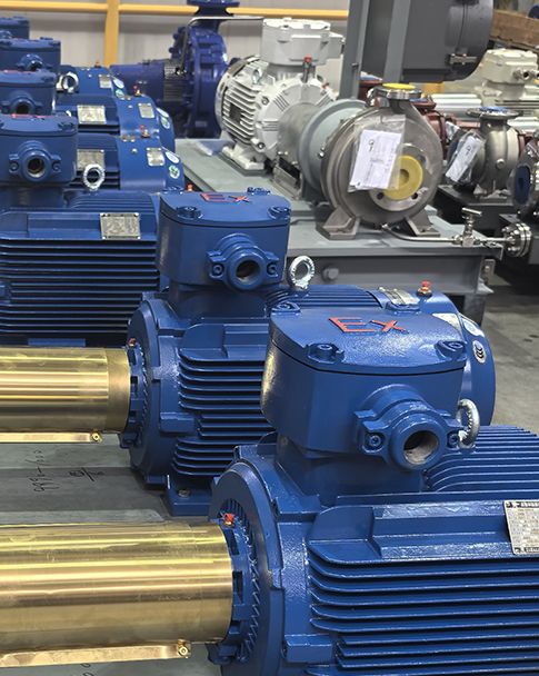
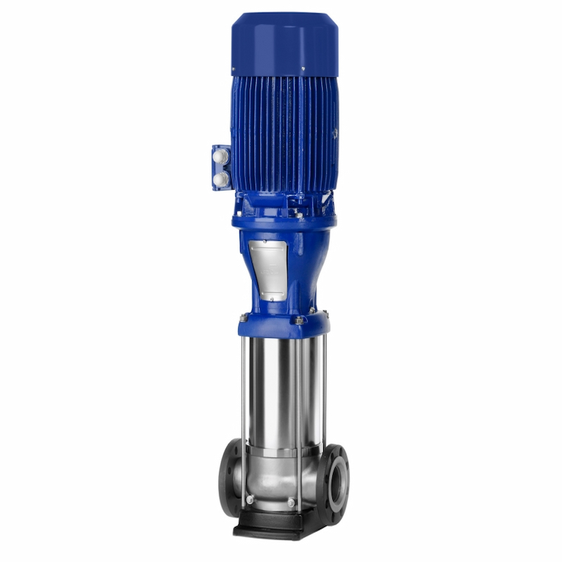
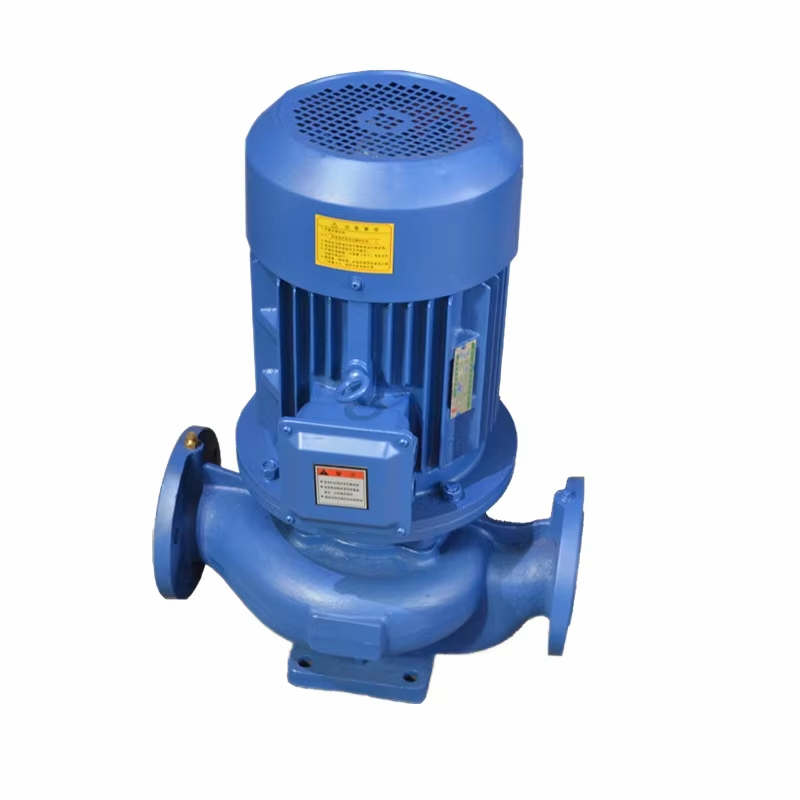
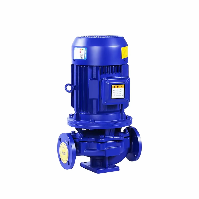
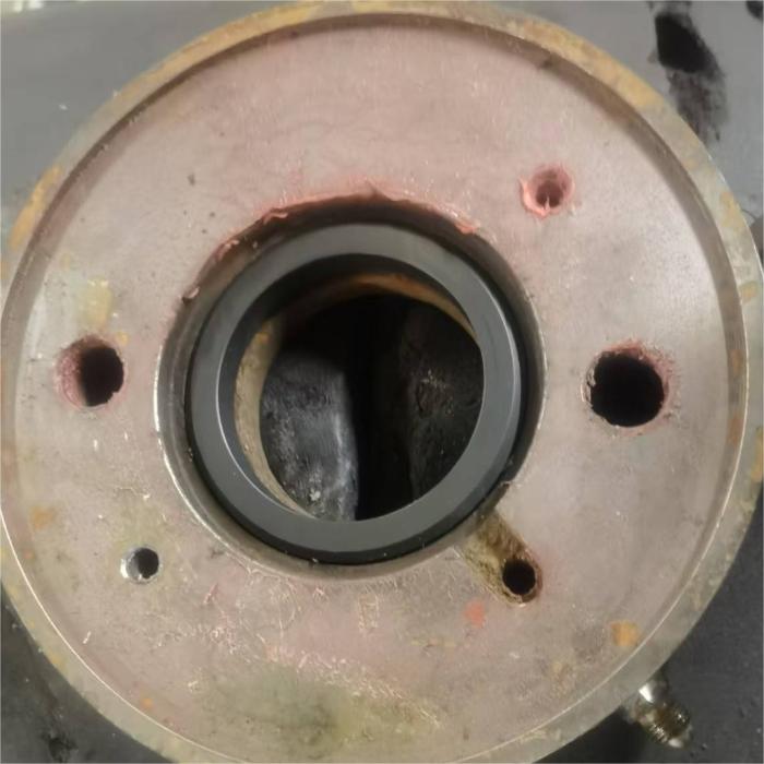
In industrial production, building water supply, agricultural irrigation, HVAC circulation, and other scenarios, pumps serve as core fluid transportation equipment. Any shutdown, leakage, abnormal noise, or failure to deliver water can mildly disrupt production and daily life, or severely lead to equipment damage and system failure. Check for water flow stability: Corresponding to inspect issues such as air entrapment, blockage, and valve closure. Check for abnormal noise from the motor: This helps identify faults such as bearing wear, cavitation, or looseness. Check for pump body overheating: Corresponding to troubleshooting overload, phase loss, poor heat dissipation, etc. Check whether voltage and current are normal: This corresponds to electrical faults such as locked electrical circuits and motor windings. In fact, there is a standardized and rapid procedure for diagnosing water pump failures. Without requiring specialized instruments or disassembling the entire unit, the fault can be pinpointed through four steps: visual inspection, auditory examination, tactile assessment, and measurement. 一、Principle of prioritization: For pump fault diagnosis, prioritize electrical components over mechanical parts, and external components over internal ones. 1.Throttle Clearance 2.Discharge Nozzle 3.Pump Cover 4.Shaft 5.Motor Cover 6.Suction Connection 7.Impeller 8.Shaft Sleeve .9Drive Sleev 10.Rolling Bearing No. English Name Chinese Name 1 Throttle Clearance 2 Discharge Nozzle 3 Pump Cover 4 Shaft 5 Motor Cover 6 Suction Connection 7 Impeller 8 Shaft Sleeve 9 Drive Sleeve 10 Rolling Bearing The key to rapid assessment lies in minimizing disassembly and maximizing inspection, progressing from simple to complex procedures, and avoiding unnecessary disassembly. Two golden principles should be remembered: 1. Electrical issues before mechanical ones: Prioritize inspection of power supply, wiring, control systems, and protective devices. Ninety percent of "non-start" incidents are electrical in nature, not due to pump failure. 2. External inspection before internal inspection: Start with valves, pipelines, filters, liquid levels, and bottom valves for preliminary troubleshooting, followed by examination of internal components such as pump bodies, impellers, bearings, and seals. Whether it's a centrifugal pump, self-priming pump, submersible pump, pipeline pump, or circulation pump, the root cause of failures remains consistent across all types, allowing for rapid troubleshooting through this standardized approach. 二、 Four Major Core Failures: Symptoms + Causes + Rapid Diagnosis Method Fault 1: The water pump fails to start completely with no response whatsoever This is the most common fault. The first on-site response should not involve pump disassembly; instead, prioritize checking the power supply and control systems. -Rapid judgment steps 1. Inspect the power supply: Check if the circuit breaker, residual current device (RCD), and fuse have tripped/fused, and whether the indicator lights are illuminated; 2. Inspection and control: Check for alarms in contactors, thermal relays, and frequency converters, as well as malfunctions in buttons, float balls, and pressure switches; 3. Electrical measurement: Use a multimeter to check voltage (whether the three-phase 380V is balanced and the single-phase 220V is normal), and inspect wiring terminals for looseness or phase loss. 4. Coupling inspection: After power-off, manually rotate the coupling/fan. If rotation is impossible, it indicates impeller jamming, bearing seizure, or foreign object ingress in the pump. -Core conclusions: No response + smooth winding = electrical circuit failure; No response + winding jam = mechanical locked rotor. Fault 2: The water pump can rotate but fails to discharge water/has extremely low flow rate/cannot increase pressure The most troublesome issue for users, "idle operation without work," is primarily caused by air lock, blockage, reverse rotation, and suction faults. -Rapid judgment steps 1. Inspect import and export conditions: Check if the imported valve is fully open, whether the filter screen is clogged, if the bottom valve is leaking or stuck, and if the liquid level is below the suction inlet. 2. Air binding: Failure to priming the centrifugal pump before startup or air leakage in the suction line can result in air accumulation within the pump, causing violent oscillations of the pressure gauge and abnormal readings on the vacuum gauge. 3. Check the rotation direction: If the phase sequence of the three-phase pump is reversed, the impeller will rotate in the wrong direction, resulting in idling without water extraction. This can be verified by swapping any two phases. 4. Internal inspection: Impeller wear, excessive clearance of the mouth ring, and pipeline scaling can lead to continuous decline in flow rate and pressure. -Core conclusion: Pressure gauge vibration = intake/gas binding; normal pressure with no water discharge = outlet blockage/valve not open; reverse rotation + no flow = phase sequence error. Fault 3: Abnormal noise + significant vibration, resembling the shaking of a 'tractor' Abnormal vibration serves as a fault warning signal. Delayed action may lead to bearing damage, shaft bending, and oil/water leakage from the machine seal. -Rapid judgment steps 1. Listen to the sounds: High-frequency screeching = bearing wear/oil deficiency; Muffled rumbling = loose foundation feet, uneven base, misalignment of coupling; Explosive sounds = cavitation; 2. Tactile vibration: Upon palpation of the pump body, motor, and base, significant shaking indicates rotor imbalance, impeller foreign body obstruction, or pipeline stress-induced tension. 3. Cavitation detection: Excessively low inlet pressure, excessively high suction head, or elevated medium temperature can generate pitting cavitation sounds accompanied by flow rate fluctuations. 4. Check installation: Misalignment of the coupling, belt pulley misalignment, or failure of vibration damping pads can all lead to resonance. -Core conclusions: Screeching = bearing problem; rumbling = looseness/alignment; popping = cavitation; vibration = imbalance/pipe stress. Fault 4: Pump body/motor overheating, burning sensation, or even tripping Overheating is a direct manifestation of overload, phase loss, friction, and poor heat dissipation. Continued operation may lead to winding burnout and bearing failure. -Rapid judgment steps 1. Temperature measurement: If the motor housing temperature exceeds 60°C (with no hand contact lasting 3 seconds) or the bearing area becomes overheated, immediately shut down the machine. 2. Current detection: Measure operating current with a clamp meter. Exceeding rated current indicates overload (due to blockage, impeller jamming, or mismatched head); low current indicates idling or air binding. 3. Mechanical inspection: Bearing oil deficiency, damage, pump shaft bending, and excessive tightness of the machine seal can all increase frictional heat generation. 4. Electrical inspection: Three-phase phase loss, low voltage, and winding short circuit are the most hazardous causes of motor overheating. -Core conclusions: High current + overheating = mechanical overload/blockage; Normal current + overheating = bearing/heat dissipation/electrical fault. Fault 5: Leakage of water/oil at the machine seal/packing area Seal leakage is a wear-related failure. If minor leaks are left untreated, they may escalate into major leaks and even damage the shaft sleeve. -Rapid judgment steps 1. Identify leakage points: dripping water at pump shaft position = packing wear/sealing aging; leakage at flange/interface = gasket damage/bolts loosening. 2. Check the packing material: Rapid dripping or premature drying of the stuffing box indicates improper installation. The normal rate should be 30-60 drops per minute. 3. Machine seal inspection: Dry rotation, particulate impurities, and misalignment can rapidly damage the mechanical seal, resulting in jet-like leakage. -Core conclusion: Drip leakage = normal wear; Spray leakage = mechanical seal failure/sleeve damage. 三、 General Rapid Assessment Mnemonic: Memorize on-site to avoid detours To facilitate on-site memory, the core diagnostic logic is summarized into a 16-character mnemonic: Do not check electricity if no ignition occurs, do not check gas if no water supply; Abnormal noise indicates shaft issues, overheating suggests load overload. Extended practical mnemonic: If the disc rotates but doesn't move, it must be stuck. -Pressure gauge vibration indicates air intake. -Three-phase reversal phase-shifting line -Bearing squeals: replace oil promptly For overheat trip, first check the current. 四、 On-site Rapid Screening Procedure 1. Power outage safety: Implement circuit breaker tripping and signage to ensure operational safety; 2. Visual inspection: Check for leaks (water/oil), wiring, valves, filters, and liquid level. 3. Manual turntable operation: Check for mechanical jamming; 4. Power-on test: listen for sounds, palpate vibrations, and observe pressure/flow rate; 5. Instrument measurement: measure voltage and current, and identify electrical/mechanical faults; 6. Precise troubleshooting: Avoid blind pump disassembly; first resolve external and electrical issues. This workflow covers over 95% of on-site faults, requiring neither experience nor disassembly, enabling even novice users to make quick diagnoses. 五、 Daily Prevention: Minimizing failures is more critical than rapid diagnosis Rapid fault diagnosis is akin to 'firefighting,' while routine maintenance serves as 'fire prevention.' By implementing these measures, pump failure rates can be reduced by 80%. 1. Regular cleaning: Import filters, impellers, and pipelines to prevent clogging by debris; 2. Standardized startup procedure: The centrifugal pump must be primed and vented to eliminate air entrainment. 3. Regular lubrication: Add or replace oil in bearings as scheduled to maintain lubrication status; 4. Alignment inspection: Regularly tighten the coupling, base, and anchor bolts. 5. Monitoring parameters: Focus on current, pressure, temperature, and vibration, with early intervention for abnormalities; 6. Prevent idling: Idling is the 'top killer' of machine seals, bearings, and impellers. 六、 Faults Are Not to Be Frightened: Methods for Diagnosis Exist As a general-purpose equipment, pump failures are predominantly caused by improper operation, lack of maintenance, and external factors, with pump body damage itself accounting for a relatively low proportion. By mastering the four-step method of "inspection, listening, palpation, and measurement" and adhering to the principle of "electricity before machinery, exterior before interior," on-site rapid localization and troubleshooting can be achieved, thereby avoiding downtime losses and reducing maintenance costs. This evaluation method applies universally to various scenarios, including factory operations and maintenance, property utilities (water and electricity), agricultural irrigation, and HVAC systems.
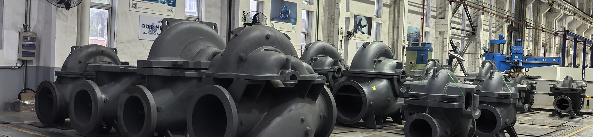
Abnormal vibration of pumps is a key indicator for assessing their reliability. Multiple factors can cause multi-stage pump vibrations, including water flow conditions, fluid motion complexity, dynamic-static balance, and high-speed rotating components—all of which may compromise pump stability. Below is a comprehensive analysis of the causes of pump vibrations. 1. Axis Pump shafts are excessively long, making them prone to dynamic friction between moving components (driving shaft) and stationary parts (sliding bearings or mouth rings) due to insufficient pump stiffness, excessive deflection, or poor shaft alignment. This friction causes pump vibration. The extended shaft length also amplifies vibrations in the submerged section of multi-stage pumps when exposed to water flow impacts. Additionally, excessive clearance in the shaft balance disc or improper adjustment of axial movement can induce low-frequency shaft oscillations, resulting in bearing vibration and rotational shaft eccentricity, which may further lead to shaft bending vibrations. 2、Foundation and Pump Support The contact fixation method between the drive unit frame and foundation is suboptimal, resulting in inadequate vibration absorption, transmission, and isolation capabilities of both the foundation and motor system. This leads to excessive vibration levels in both components, causing the pump foundation to loosen. During installation, the pump unit may form an elastic foundation or experience reduced foundation stiffness due to oil immersion cavitation, triggering a critical rotational speed with a 180-degree phase difference from the vibration. This increases the pump's vibration frequency, and if the increased frequency aligns with an external factor's frequency, it amplifies the amplitude of the multistage pump. Additionally, loose foundation anchor bolts decrease restraint stiffness, exacerbating motor vibration. 3. Coupling Improper circumferential spacing of coupling bolts, compromised symmetry, eccentricity in the coupling's extension section, excessive taper tolerance, poor static or dynamic balance, overly tight elastic pin coupling, loss of elastic pin's self-adjusting function causing misalignment, excessive shaft coupling clearance, mechanical wear of the coupling rubber ring leading to reduced sealing performance, and inconsistent quality of transmission bolts used in the coupling—all these factors can cause vibration in multi-stage pumps. 4. Factors inherent to the water pump itself The asymmetric pressure field generated during impeller rotation; vortex formation in suction tanks and intake pipes; vortex generation and dissipation within the impeller, volute, and guide vanes; valve half-open-induced vortex-induced vibration; uneven outlet pressure distribution due to limited impeller blade count; flow separation within the impeller; surge; pulsating pressure in flow channels; cavitation; water flow in the pump body causing friction and impact, such as water impacting the tongue and leading edges of guide vanes, resulting in vibration; boiler feed pumps handling high-temperature water are prone to cavitation-induced vibration; pressure pulsations in the pump body, primarily caused by excessive clearance between the impeller seal ring and pump body seal ring, leading to significant internal leakage, severe backflow, and subsequent unbalanced axial force on the rotor and pressure pulsations, which intensify vibration. Furthermore, for stainless steel hot water pumps used in hot water delivery systems, uneven preheating prior to startup or malfunctioning sliding pin systems can cause thermal expansion in the pump assembly, triggering severe vibrations during the startup phase. If internal stresses from thermal expansion cannot be released, this may alter the stiffness of the shaft support system. When the modified stiffness becomes a multiple of the system's angular frequency, resonance occurs. 5. Motor Loose motor structural components, loose bearing positioning devices, excessively loose silicon steel sheets in the iron core, and reduced bearing support stiffness due to wear can all cause vibrations. Eccentric mass distribution, rotor bending, or uneven mass distribution resulting from quality issues may lead to excessive static and dynamic balance deviations. Additionally, broken squirrel-cage bars in the rotor of squirrel-cage motors can cause vibrations due to an imbalance between the magnetic force acting on the rotor and its rotational inertia. Other contributing factors include phase loss in the motor and power supply imbalance across phases. Regarding the stator windings, poor installation quality may lead to resistance imbalance between phases, resulting in uneven magnetic field distribution. This creates unbalanced electromagnetic forces that act as excitation forces, ultimately triggering vibrations. 6. Pump Selection and Variable Operating Conditions Every pump has its own rated operating point. Whether the actual operating conditions match the design specifications significantly impacts the pump's dynamic stability. While pumps operate more stably under design conditions, variable operating conditions can cause increased vibration due to radial forces generated in the impeller. Factors such as improper single-pump selection or parallel operation of mismatched pump models may all contribute to vibration in multi-stage pumps. 7. Bearings and Lubrication Insufficient bearing stiffness reduces the first critical speed, leading to vibration. Poor performance of guide bearings, such as inadequate wear resistance, improper fixation, or excessive bearing bush clearance, can also cause vibrations. Additionally, wear in thrust bearings and other rolling bearings may intensify both axial movement and bending vibrations. Lubrication failures—such as improper lubricant selection, degraded oil, excessive impurities, or clogged lubrication lines—can worsen bearing conditions and trigger vibrations. Self-excited vibrations in motor sliding bearing oil films may also contribute to operational instability. 8. Pipelines and Their Installation and Fixation The pump's outlet pipeline support lacks sufficient rigidity, causing excessive deformation that presses the pipeline against the pump body. This results in misalignment damage between the pump body and motor. During installation, the pipeline experiences excessive force, leading to high internal stress when connecting the inlet and outlet pipes to the pump. Loose connections in the inlet and outlet pipelines reduce or even nullify the restraint rigidity, causing partial or complete fracture of the outlet flow channel. Broken fragments may get lodged in the impeller, obstructing the pipeline. Issues such as air pockets at the outlet, missing or improperly opened water discharge valves, air intake at the inlet, uneven flow fields, and pressure fluctuations can directly or indirectly cause vibrations in the multistage pump and its pipelines. 9. Fit between components The motor shaft and pump shaft exhibit concentricity deviations. A coupling is used at the motor-pump shaft connection, but its concentricity is out of specification. This causes increased wear on the designed clearance between moving and stationary components (e.g., between the impeller hub and the mouth ring). Additionally, the clearance between the intermediate bearing bracket and the pump cylinder exceeds the standard, while the sealing ring clearance is improperly adjusted. These factors collectively create imbalance, resulting in uneven clearance around the sealing ring. Issues like the mouth ring not fitting into the groove or the partition plate not aligning with the groove can lead to such problems. All these adverse factors contribute to the vibration of the multistage pump. 10. Impeller The pump impeller's eccentricity stems from inadequate quality control during manufacturing, such as casting defects or insufficient machining precision. When handling corrosive liquids, the impeller's flow channels may be eroded, causing misalignment. Key factors include proper blade count, optimal outlet angle, appropriate wrap angle, and correct radial spacing between the throat tongue and impeller outlet edge. During operation, initial contact between the impeller's mouth ring and the pump body's mouth ring, along with friction between stage bushings and partition bushings, evolves from initial contact to mechanical wear, ultimately exacerbating the pump's vibration.
Why is your pump more power-hungry? The common problem of 'same pump, my pump consumes more electricity' is usually not caused by a single factor, but by a series of 'pre-existing faults' working together. Put simply: two pumps that appear identical may perform vastly differently in efficiency when installed, maintained, or operated under varying conditions, resulting in significant variations in power consumption. 一、Installation and pipeline system failures 1. This is a common issue. The pump's power consumption is largely used to overcome the resistance of the pipeline system. 2. Insufficient pipe diameter or excessive length: Using smaller pipes than designed to cut initial costs, or an inefficient pipeline layout that increases length, can significantly raise flow resistance. This forces the pump to expend more energy to push the water. 3. Excessive valves and elbows: Each valve, elbow, or tee creates localized resistance. Unnecessary partially open valves and the use of right-angle elbows instead of rounded ones act like roadblocks, forcing the pump to expend more power to maintain flow. 4. Poor import conditions: The imported pipeline has reduced diameter, sharp bends or is too close to the pool wall, which may cause cavitation in the pump. Cavitation not only damages the impeller but also severely reduces pump efficiency, wasting a lot of electrical energy on cavitation and vibration. 二、Pump and System "Water and Soil Unadaptability" 1. The pump's operating point (flow rate and head) is determined by its performance curve and the pipeline's characteristic curve. Mismatch is the biggest efficiency killer. 2. Excessive head selection (a common issue): When a pump with 40-meter head is installed for a 30-meter head requirement, it operates outside its optimal efficiency range. This forces operators to reduce flow by partially closing the outlet valve, artificially increasing pipeline resistance. The excess head (energy) is wasted on the valve, resulting in a dramatic rise in power consumption. 3. "Big horse pulling a small cart" or "small horse pulling a big cart": When the motor's power is mismatched with the pump, or when the pump's rated flow rate far exceeds actual needs, it results in low operational efficiency. 三、 The "Health Deterioration" of Pump Body Even if installed correctly, long-term wear and lack of maintenance can lead to problems. 1. Wear of key components Impeller wear: When conveying liquid containing particles, the impeller gradually wears down, causing its profile to change and reducing energy transfer efficiency. Sealing ring or port ring wear: This component prevents high-pressure water from the pump from flowing back into the low-pressure area. When wear widens the clearance, internal leakage increases, causing a significant portion of the pump's work to be consumed by internal circulation, thereby greatly reducing its effective output. 2. Mechanical problems Axial misalignment or poor alignment (improper coupling alignment) can cause additional friction and vibration, leading to energy loss. Bearing damage: the rotation is not smooth and the friction is increased. The mechanical seal or packing seal is too tight, which increases unnecessary friction resistance. 四、The "Acquired Neglect" of Operation and Maintenance 1. Never conducted efficiency tests: The principle was 'as long as it works,' with no measurement of actual flow, pressure, or current during operation. Comparing these with the pump's original performance curve failed to detect the gradual decline in efficiency. 2. Inadequate maintenance: Failure to regularly inspect and replace worn parts, clean filters, or ensure proper lubrication allows minor issues to escalate into major problems. 3. Change of transport medium: The viscosity and impurity content of water are higher than designed, which will increase the load of the pump. Steps to solve the problem: 1. System inspection: First, inspect the piping system to ensure all valves are fully open, check for filter blockages, and evaluate the rationality of the pipeline layout. 2. Operating condition measurement: Install pressure gauges at the pump's inlet and outlet to measure actual head; determine methods to measure actual flow rate; record operating current. 3. Data Analysis: Plot the actual head and flow rate on the pump's original performance curve to determine if the operating point falls within the high-efficiency zone. Calculate the current efficiency. 4. Pump inspection: If the above steps involve the pump itself, disassemble and inspect components like the impeller and sealing rings for wear, then repair or replace them. 5. Consider technical upgrades: For pumps with severe mismatch (e.g., those relying on valve regulation for extended periods), the most effective solution is to replace them with appropriately sized pumps or install variable frequency drives (VFDs). This ensures precise matching of pump operating parameters to actual needs, thereby eliminating throttling losses. In short, the "same pump" is merely a superficial phenomenon. Every stage from selection, installation, commissioning to maintenance may harbor the seeds of increased power consumption. The solution lies in systematic diagnosis, tracing from the pipeline to the pump body to identify the true "efficiency funnel".


 IPv6 network supported.