What are the advantages of stainless steel pumps? Introduction to common stainless steel pumps
Jan 05, 2026
What are the advantages of stainless steel pumps?Introduction to common stainless steel pumps
When transporting weak acid, weak alkali, salt and other media, the corrosion resistance of stainless steel pump is significantly better than that of other materials, but the price of stainless steel pump is slightly higher.
When transporting weak acid, weak alkali, salt and other media, the corrosion resistance of stainless steel pump is significantly better than that of other materials, but the price of stainless steel pump is slightly higher. As the saying goes, price equals price, so what are the highlights of stainless steel pumps compared with other materials?
stainless steel pumps are very resistant to corrosion and, more importantly, very durable. Stainless steel pumps are usually mainly used in different working and living environments in various ways, some of these social and environmental problems need to be corrosion-resistant, and some enterprises need our stronger drainage design capabilities, stainless steel pumps are made of high-strength stainless steel raw materials, which have strong corrosion resistance, and the use of pumps for this teaching material, there is no need to worry that the effect of the pump will be affected by the external economic environment, which is a stainless steel pump can be more suitable for students in various harsh environments, and continue to work healthily and stably.
stainless steel pumps are a little more expensive in their class, but their performance is impeccable. Stainless steel pumps have been products in the industry to occupy a position, and its cost-effective nature is self-evident.
stainless steel water pump can operate stably for a long time, the failure rate is very low after use, and the later maintenance is also very simple, which can meet the requirements of users for long-term use. Stainless steel pumps can convey a variety of different media, from tap water to industrial liquids, stainless steel pumps through stainless steel flow plate stamping process, adapt to different temperatures, flow rates and pressure ranges, stainless steel pumps are non-corrosive or lightly corrosive liquids, can transport temperatures up to 120
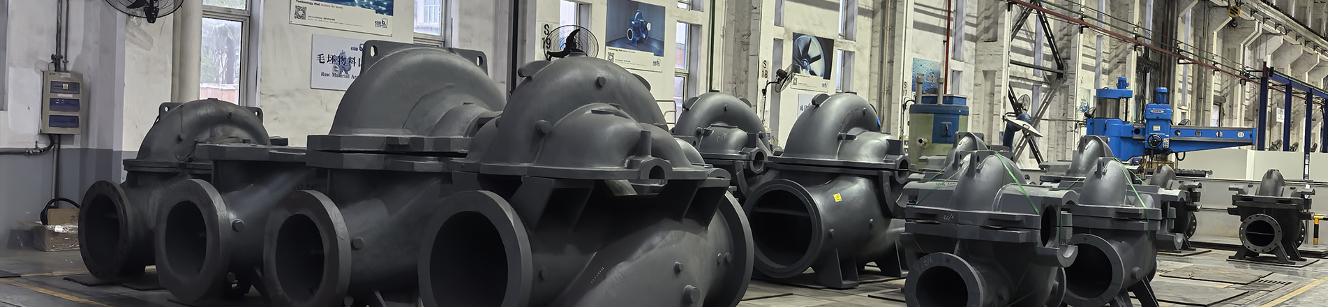
Common stainless steel pumps
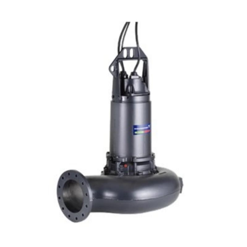
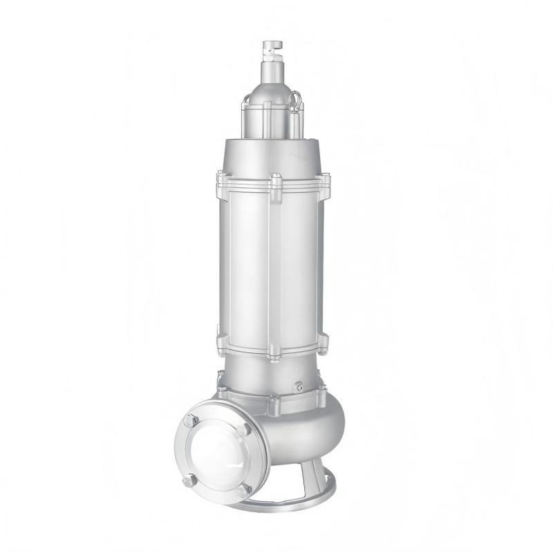
Stainless steel sewage submersible pump
Flow: 10~2800m³/h
Head:6~75m
Power:0.75~250kW
Product description:
1. Adopting stainless steel precision casting shell, it has the characteristics of corrosion resistance,environmental protection,high lift, and large flow rate.
2. The oil chamber adopts a double-sided mechanical seal made of fluororubber, while the outer chamber adopts a single-sided fluororubber mechanical oil seal structure, effectively reducing the problem of sealing water ingress caused by friction between the skeleton oil seal and the shaft.
3. The motor adopts high-temperature wire, F-class insulation, and thermal protection device, effectively extendina the service life of the pump.
4. According to customer requirements, a mixing device can be equipped, which generates a strong mixing force with the rotation of the motor shaft, stirring the sediment in the sewage tank into suspended solids and then discharging them. It can also be equipped with a cutting device, which can remove debris such as long fibers, plastic, paper bags, and straw from the sewage
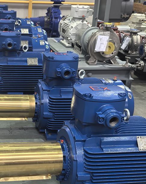
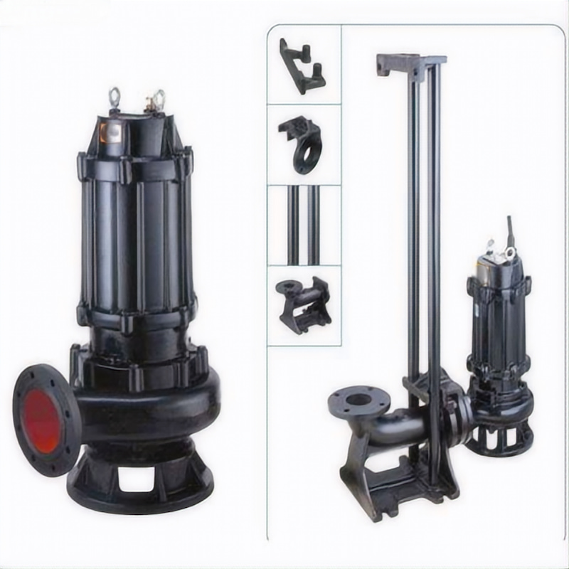
Stainless steel explosion-proof sewage submersible pump
Flow:7-220m³/h
Head: 6-60m
Power:0.75-15kw
Product description
1.Adopting stainless steel precision casting shell, it has the characteristics of corrosion resistance, environmental protection,high lift, and large flow rate.
2. The oil chamber adopts a double-sided mechanical seal made of fluororubber, while the outer chamber adopts a single-sided fluororubber mechanical oil seal structure, effectively reducing the problem of sealing water ingress caused by friction between the skeleton oil seal and the shaft.
3. The motor adopts high-temperature wire, F-class insulation, and a thermal protection device, effectively extending the service life of the pump.
4、According to customer requirements, a mixing device can be equipped, which generates a strong mixing force with the rotation of the motor shaft, stirring the sediment in the sewage tank into suspended solids and then discharging them. It can also be equipped with a cutting device, which can remove debris such as long fibers, plastic, paper bags, and straw from the sewage.
5. The explosion-proof level is Ex db llB T4 Gb.
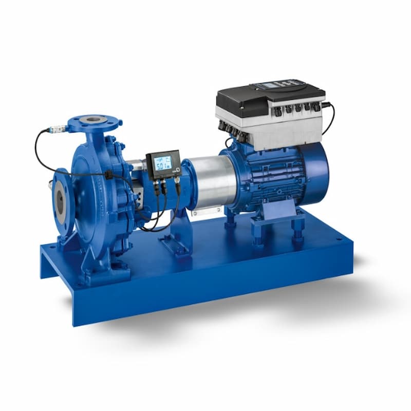
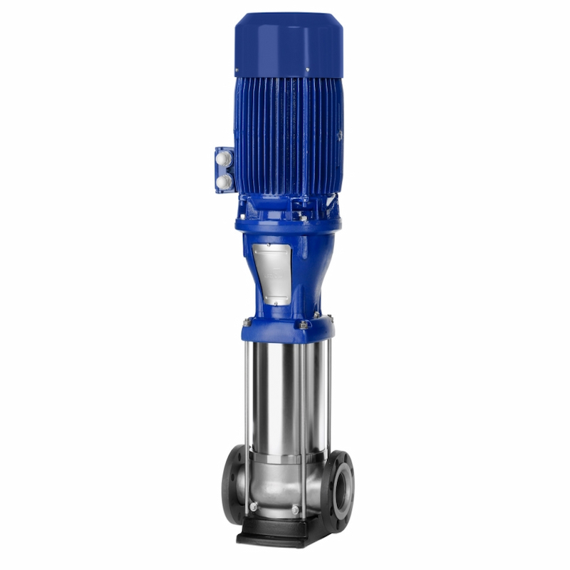
Light vertical multistage centrifugal pump
Flow: 2~240 m³/h
Head: 15~305 m
Power: 0.37~110 kW
Product Description:
CDL(F) is a multifunctional product, capable of transporting various media, from tap water to industrial liquids, suitable for different temperatures, flow rates, and pressure ranges. CDL (f) is suitable for mildly corrosive liquids.
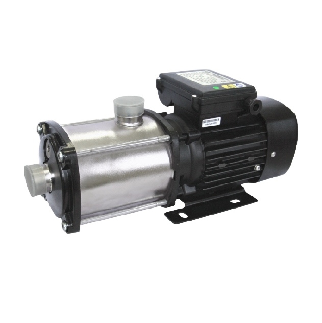
Horizontal multistage stainless steel centrifugal pump
Flow: 0.5-26m³/h
Head: 7-52m
Power:0.37- 4.0kw
Characteristics:
horizontal multi-stage stainless steel centrifugal pumps are manufactured through advanced processes such as stamping and welding using stainless steel (SS304) plates. They have the characteritics of being lightweight, aestheticalh pleasing, material-saving, and highly efficient, Their performance reaches the advanced level of similar products.
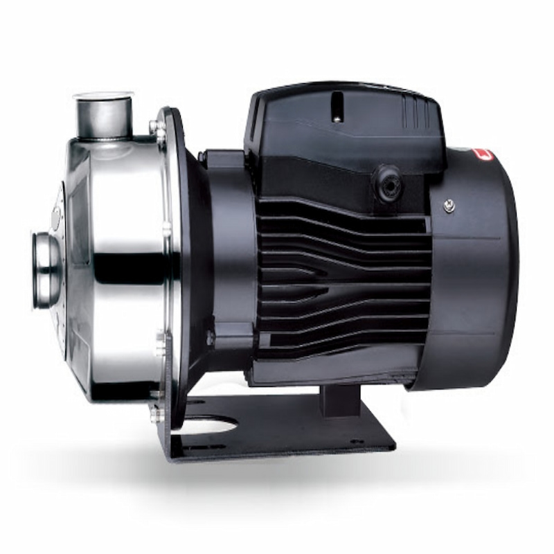
Stainless steel self-priming corrosion-resistant miniature electric pump
Flow: 3-15m³/h
Head: 8-22m
Power: 0.25-3kw
Characteristics:
1.Strong self-priming ability: There is no need to pour in priming water. It can automatically suck in the liquid after starting, which is convenient to use.
2.Good corrosion resistance: Made of stainless steel material, it can resist a variety of corrosive media and has a wide range of applications.
3.Compact size: With a compact structure, it takes up little space, making it easy to install and move.
4.Stable operation: With reliable performance, low noise and small vibration, it can work stably for a long time
5.Easy maintenance: With a simple structure and few components, it is easy to disassemble and repair.
Read More


 IPv6 network supported.