Water,How does it ensure the continuous operation of industries?
Jul 02, 2026
Let every drop of industrial water...
Accurately access the critical process
In industrial settings, many critical processes appear to be driven by steel, equipment, and automation systems. However, what truly permeates these processes is often a fundamental yet most essential medium—water.
From equipment cleaning and system flushing to cooling, heat transfer, boiler feedwater, as well as process water and product water in industries such as food and beverage, pharmaceuticals, and semiconductors, treated water is present in virtually every modern industrial process. The stability of water quality directly impacts equipment performance, product quality, energy consumption levels, and system reliability.
Why does industry require water treatment?
Just as human survival depends on water, industrial operations likewise require water to participate in various processes.
In fundamental applications, water is commonly used for equipment cleaning and system flushing. Many industrial installations require regular cleaning or flushing to ensure stable operation.
Water is also commonly employed as a cooling medium to prevent equipment overheating, functioning similarly to coolant in automotive cooling systems. Additionally, it serves as an excellent heat transfer medium, particularly suitable for applications requiring maintenance of specific temperature ranges during industrial processes. Due to its inherent physical properties and ease of handling, water stands out as one of the most ideal heat transfer media across the 0–100°C temperature range.
In applications requiring higher temperatures, water can also serve as feedwater for boiler systems to generate steam, thereby providing heat for industrial processes, or be utilized in power plants for energy conversion.
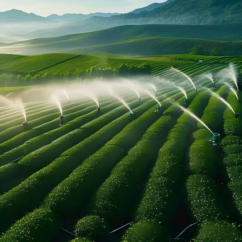
Furthermore, water can be directly utilized as process water or product water in the manufacturing of industrial products. For instance, in the food and beverage industry, water is not only employed for cleaning but may also serve as an integral component of the final product itself.
Industrial production demands substantial water resources: producing one ton of steel requires approximately 200,000 liters of water, while manufacturing one ton of paper necessitates about 400,000 liters. According to data from the German Environment Agency, Germany's chemical industry alone consumed nearly 2.6 billion cubic meters of water for product manufacturing in 2016, accounting for roughly 58% of the country's total industrial water usage.
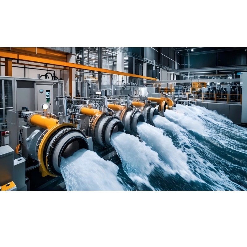
Industrial water
More than just water supply
The complexity of industrial water usage lies in the fact that different processes require entirely distinct water qualities.
The water used for cleaning equipment does not need to meet the purity requirements specified for pharmaceutical production; likewise, the water employed in cooling systems differs from the ultrapure water utilized in semiconductor manufacturing.
Therefore, the core of industrial water treatment lies not merely in "making water clean," but in delivering water to appropriate, stable, and controllable quality levels tailored to specific application scenarios.
What are the different types of water quality required for industrial applications?
Different industrial applications have varying requirements for water quality. Water used for cleaning equipment clearly does not need to meet the water quality standards required for hospital infusion products.
The purity of water can be measured in various ways, such as by determining the mass of dissolved substances, changes in boiling or freezing points, or through refractive index measurements. However, the most commonly employed method is the determination of water conductivity.
This is because the lower the concentration of dissolved salts in water, the higher its chemical purity and consequently the lower its conductivity. Conductivity is typically expressed in Siemens per meter. In industrial applications, common water quality grades primarily include the following categories.
Drinking water
Drinking water refers to water whose purity is strictly regulated and guaranteed by applicable laws. In Germany, drinking water quality is governed by the German Drinking Water Regulation and is typically supplied through municipal systems via conventional drinking water distribution networks.
At 25 °C, the specific conductivity of drinking water typically ranges from 50 to 5,000 μS/cm.
High-quality drinking water is widely used in the food industry, for example in food cleaning or beverage production.
Pure water or purified water
Pure water or purified water is treated drinking water that may still contain trace amounts of residual ions.
At 25 °C, the specific conductivity of pure water typically ranges from 1 to 50 μS/cm.
Pure water can be used in numerous industrial applications, including thorough cleaning of systems and equipment. Due to its low residue retention upon evaporation, it is ideal for scenarios requiring high cleanliness standards.
Fully desalinated water (deionized water) and distilled water
Fully desalinated water, also known as deionized water, refers to water in which allionic components—namely anions and cations—have been removed.
It should be noted that distilled water and deionized water are not entirely identical. There are differences between the two in terms of water quality requirements and production processes, with the primary distinctions lying in purity levels and preparation methods.
At 25 °C, the specific conductivity of fully desalinated water or distilled water typically ranges from 0.1 to 1 μS/cm.
Ultrapure water
Ultra-pure water represents the highest level of water purity, containing only trace amounts of organic compounds, microorganisms, or electrolytes.
At 25 °C, the specific conductivity of ultrapure water typically falls below 0.1 μS/cm.
Ultra-pure water can be used as rinse water or process water in medical applications, the semiconductor industry, and power plant technologies.
In practical industrial applications, common types of water include drinking water, pure water, fully desalinated water, distilled water, and ultrapure water. Water purity is typically measured by conductivity: the lower the concentration of dissolved salts in water, the lower its electrical conductivity, and consequently the higher its purity.
When water is utilized in food and beverage, pharmaceutical, energy, semiconductor, or other high-demand processes, these seemingly minor variations in water quality often become critical factors affecting production stability.
A complete system
The "multiple layers of screening" behind it
To achieve the desired water quality, industrial water treatment typically requires the coordinated application of multiple processes.
Mechanical treatment can remove impurities using grids, screens, filters, or membrane filtration; physical treatment can alter the state of substances in water through aeration, sedimentation, flotation, vacuum, or thermal effects; chemical treatment can further improve water quality via methods such as oxidation, disinfection, coagulation, ion exchange, activated carbon adsorption, osmosis, and reverse osmosis.
Among these, membrane filtration technology is commonly employed in separation processes with varying degrees of precision.
Microfiltration removes relatively coarse particles, algae, bacteria, and oil emulsions; ultrafiltration further separates viruses, pathogens, proteins, and macromolecular substances; nanofiltration eliminates certain dissolved substances and divalent ions; reverse osmosis represents a more advanced membrane filtration process that retains substantial amounts of dissolved salts, microorganisms, and contaminants under high pressure, yielding highly purified water.
What are the main methods for industrial water treatment?
Water treatment methods can generally be divided into three categories.
The first category is mechanical treatment, such as processing using grids, screens, and filters, which also includes membrane filtration technologies like microfiltration, ultrafiltration, and nanofiltration.
The second category comprises physical treatments, such as aeration, atomization, sedimentation, air flotation, vacuum processes, and thermal treatment.
The third category is chemical treatment, including processes such as oxidation, disinfection, flocculation, ion exchange, activated carbon adsorption, osmosis, and reverse osmosis.
In practical applications, these processes are typically combined based on the characteristics of the raw water and its intended use to achieve the required water quality standards.
From microfiltration, ultrafiltration, nanofiltration to reverse osmosis
During the microfiltration process, water passes through a membrane with pore sizes ranging from approximately 0.1 to 10 μm.
Depending on the application, the filtration surface may be fabricated from stainless steel, plastic, ceramic, or textile materials.
Microfiltration is widely used for beverage and oil filtration as well as pre-filtration processes. This technique typically operates under low pressure, with approximately 0.1 bar at the inlet and 2 bar at the outlet. It primarily removes relatively coarse substances from water, such as organic materials like plankton, algae, and bacteria, as well as oil emulsions. Additionally, larger colloidal particles or droplets dispersed in water can also be effectively removed through microfiltration.
The next stage is ultrafiltration. Ultrafiltration membranes typically have pore sizes ranging from 0.01 to 0.1 μm, enabling the separation of even finer particles such as viruses, pathogens, proteins, colloidal metals, or macromolecular substances. The required transmembrane pressure for ultrafiltration generally ranges from 1 to 10 bar.
Nanofiltration employs even finer pores, typically ranging from 0.01 to 0.001 μm in size. This process effectively filters dissolved substances and divalent ions (e.g., heavy metals such as zinc, magnesium, calcium, or mineral ions), while also removing larger monovalent ions (e.g., alkali metal ions like lithium, sodium, potassium) and halide ions such as chloride.
Nanofiltration can remove 50% to 90% of chlorides and sodium ions. Therefore, nanofiltration is often regarded as one of the ideal alternatives to water softening systems. The process typically requires a pressure range of 5 to 10 bar.
Reverse osmosis represents the final stage of membrane filtration technology and constitutes the most advanced filtration process.
During the reverse osmosis process, the principle of natural osmosis is utilized in reverse. Specifically, wastewater with high ion concentration is forced to permeate a semipermeable membrane under high pressure, overcoming the natural osmotic pressure. For example, in landfill leachate treatment, the pressure may exceed 80 bar.
Due to molecular size limitations, unwanted solutes cannot pass through ultra-fine membrane structures. The pore sizes of reverse osmosis membranes typically range from 0.001 to 0.0001 μm and can even retain monovalent ions. The resulting water is highly purified, containing virtually no particulate substances such as minerals, foreign particles, viruses, bacteria, pathogens, or other contaminants.
From microfiltration to reverse osmosis, water treatment functions like a sophisticated "filtering architecture": each stage has distinct functional boundaries and collectively lays the foundation for the final water quality.
industrial water conditioning
KSB's Solution
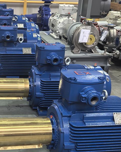
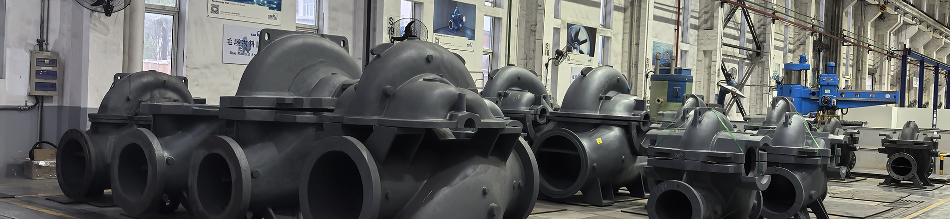
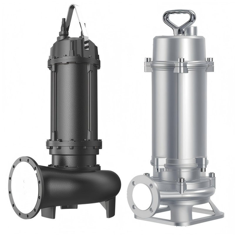
In industrial water treatment systems, pumps and valves are not merely supplementary components; they are critical elements essential for medium transportation, pressure control, system stability, and continuous operation.
Whether it's softened or desalinated water required for cooling systems, boiler feedwater for softening, decarbonization and desalination in water-steam systems, or process-specific water applications and high-purity product water applications, KSB offers tailored pump-valve solutions for diverse industrial water treatment processes.
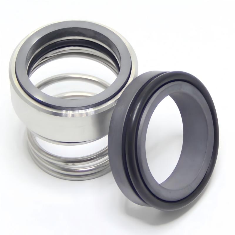
To address high temperatures, corrosive environments, and continuous operating conditions, KSB helps customers enhance system safety and stability through durable materials, reliable sealing designs, and a comprehensive product portfolio.
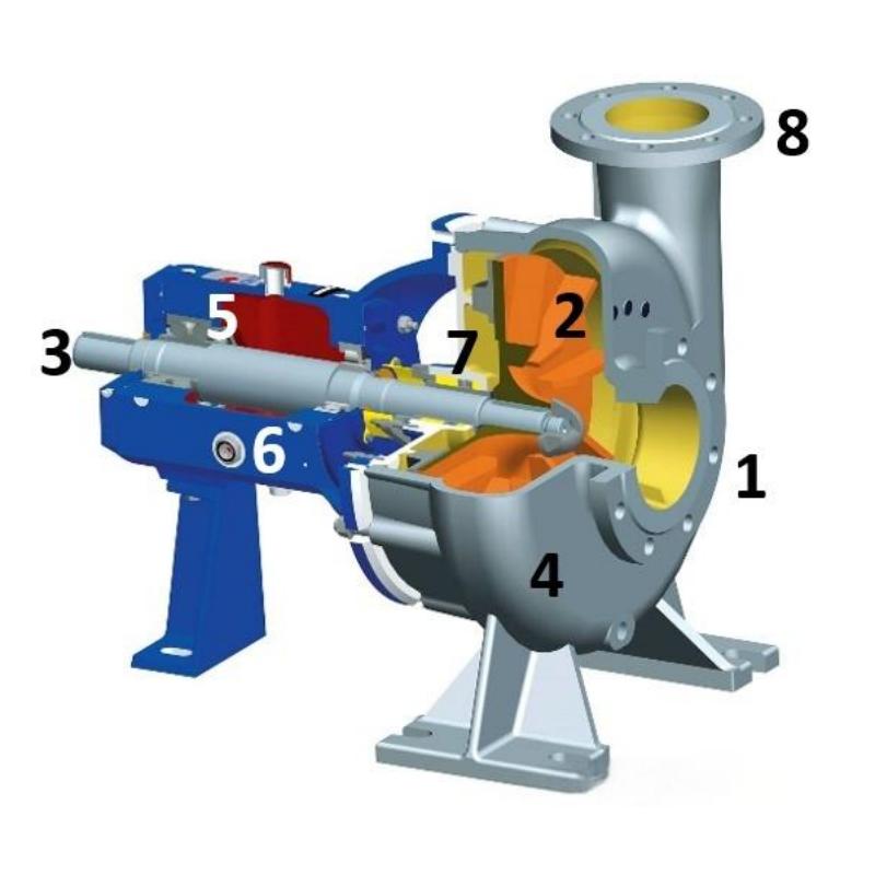
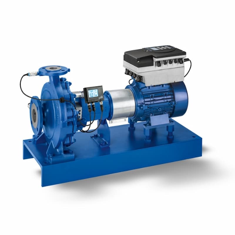
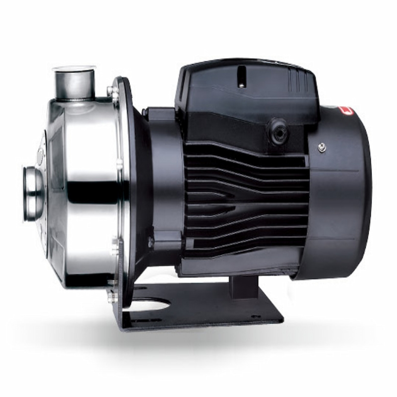
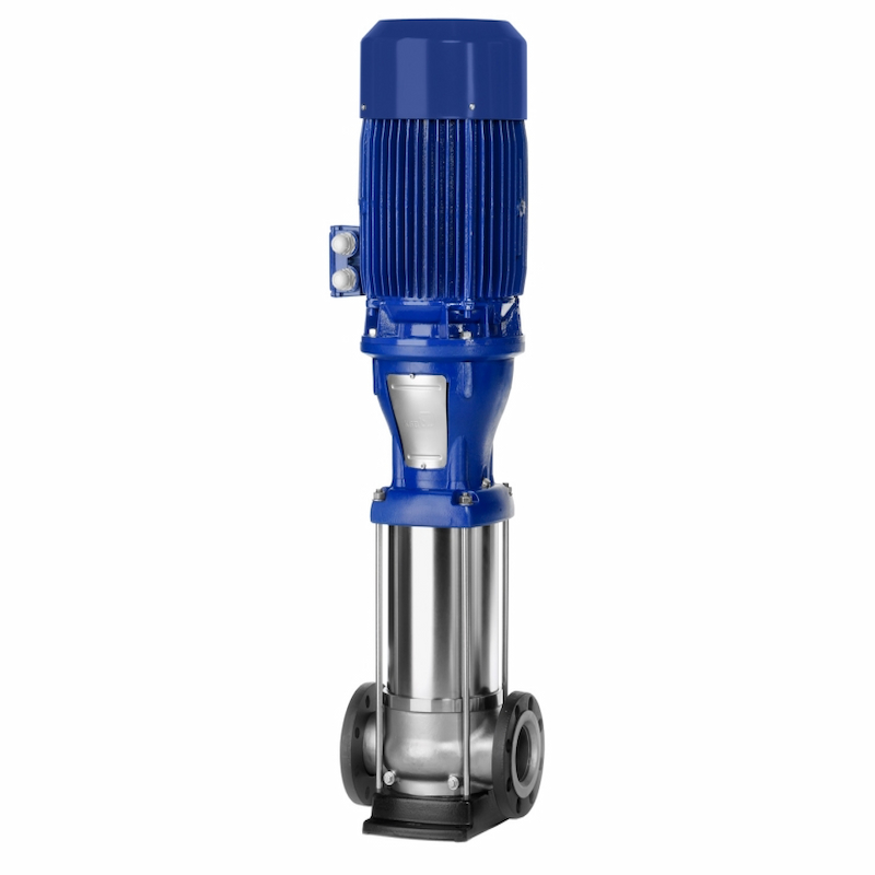
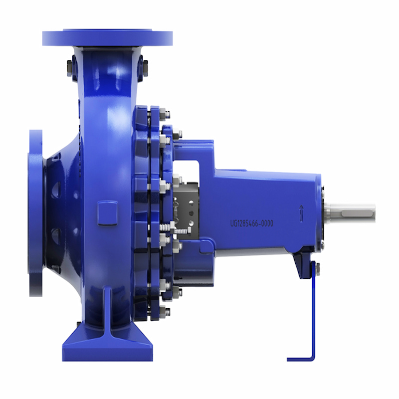
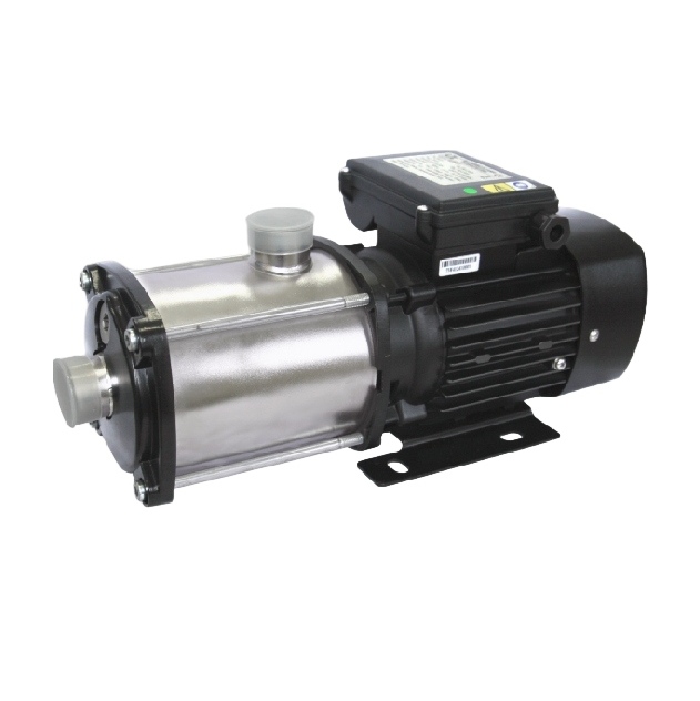
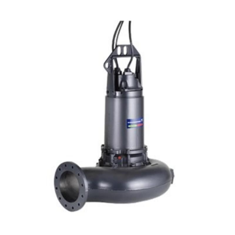
For instance, the KSB Eta series port suction pumps, as well as the Movitec and Multitec series multi-stage high-pressure pumps, can be customized to meet specific application requirements and suit various industrial water treatment scenarios.
product picture
Furthermore, leveraging its extensive expertise in industrial water treatment, KSB not only offers technologically advanced products but also provides professional consulting and service support to help clients achieve higher reliability across the entire lifecycle of systems—from selection and operation to maintenance.
The value of industrial water lies not in quantity, but in suitability: appropriate water quality for the right process; proper pressure for specific operational conditions; and suitable equipment to ensure optimal system efficiency.
This is precisely the significance of industrial water treatment, and it also reflects KSB's ongoing commitment to advancing applications in this field.
From water treatment to fluid transportation, from standalone equipment to integrated system solutions, KSB leverages its expertise in pump and valve technology along with industry knowledge to deliver stable, efficient, and reliable solutions for industrial applications.
Ensuring precise water flow in industrial processes also drives continuous production progress.
Read More


 IPv6 network supported.