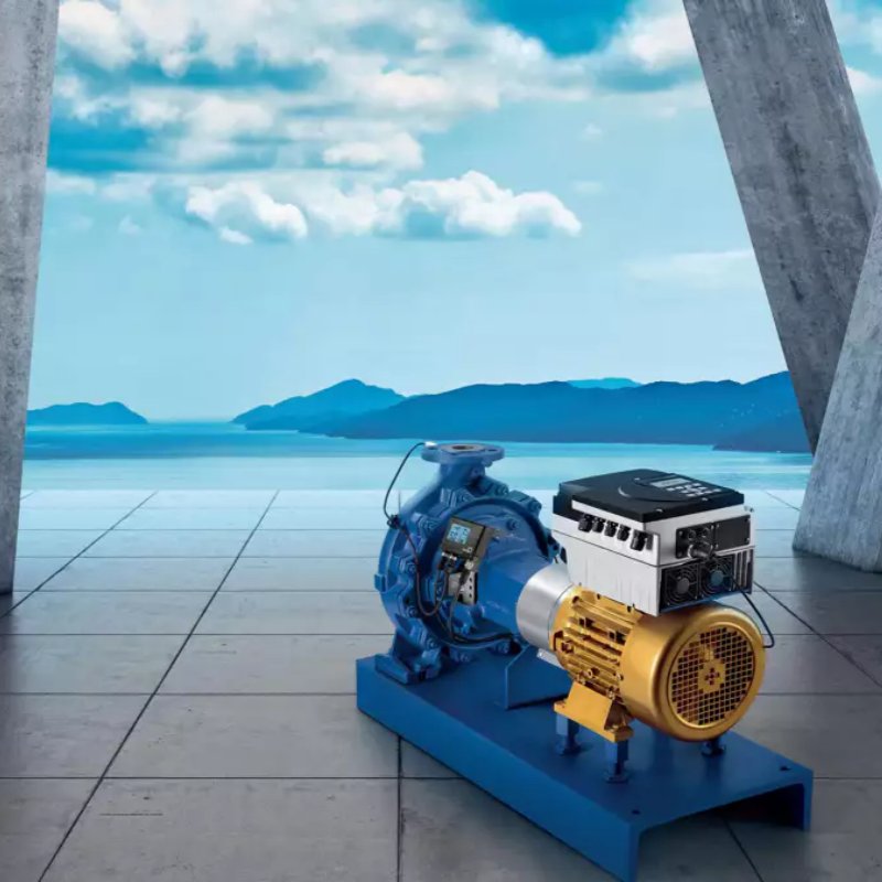
Suggestions and steps for starting and debugging centrifugal pumps
Oct 16, 2025
Basics
Regardless of pump type or application, there are basic startup steps. In this article, in addition to covering some general startup procedures, we'll also address some often-overlooked details (common mistakes) that can lead maintenance personnel and equipment to disaster. Note: All pumps mentioned in this article are centrifugal pumps.
I've witnessed some costly startup mistakes that could have been easily avoided if the operator had read and observed a few key points in the equipment's Installation, Operation, and Maintenance Manual (EOMM).
Let's start with a few basic, correct steps, regardless of pump type, model, or application.
1) Carefully review the EOMM and local facility operating procedures/manuals.
2) Every centrifugal pump must be primed, vented, and filled with liquid before startup. Pumps to be started must be properly primed and vented.
3) The pump suction valve must be fully open.
4) The pump discharge valve can be closed, partially open, or fully open, depending on several factors discussed in Part 2 of this article.
5) The bearings of the pump and driver must have the appropriate lubricant at the proper level and/or grease present. For oil-mist or pressurized oil lubrication, verify that the external lubrication system is activated.
6) The packing and/or mechanical seals must be correctly adjusted and/or set.
7) The driver must be precisely aligned with the pump.
8) The entire pump and system installation and layout are complete (valves are in place).
9) The operator is authorized to start the pump (lockout/tagout procedures are performed).
10) Start the pump and then open the outlet valve (to the desired operating position).
11) Observe the relevant instruments—the outlet pressure gauge rises to the correct pressure and the flow meter indicates the correct flow.
So far, it seems simple, but let me offer some advice. Do you initially assume you've purchased a smooth-running pump that generates the appropriate flow and head at its best efficiency point (BEP) and can be started without any problems after simple preparation? If so, you've missed several steps in the startup process described above.
We often find ourselves at a pump, unprepared for initial startup, accompanied by an impatient, inexperienced operations supervisor urging us to "start it." The problem is that there's actually a long list of items that should be completed and/or checked before that dramatic startup moment. Pumps are expensive, and it's easy to squander all that cost, or more, in the single second it takes to hit the start button.
This article will limit its discussion to the "things" required and/or recommended before startup. The more complex the pump and system, the more steps and checks are required. I won't cover more complex installations and procedures, as these operators are typically highly trained and experienced.
The decision and actions regarding the correct pump selection begin long before what we call the critical moment of startup (or what we might call "things to do before or during installation").
Preliminary work that should be completed in advance includes foundation design, grouting, pipe strain relief, ensuring adequate NPSH margins, pipe sizing and system configuration, material selection, system hydrostatic testing, monitoring instrumentation, immersion calculations, and auxiliary system configuration and requirements.
ANSI Pumps
American National Standards Institute (ANSI) pumps are one of the most common pump types in the world. Therefore, this article will explain some important aspects of this type of pump.
ANSI pumps include adjustable impeller clearance settings. There are essentially two contrasting styles, but both must be adjusted to the proper clearance before startup. The mechanical seal also requires adjustment and setting. Important: The seal must be set after the impeller clearance is set; otherwise, the settings/adjustments will be off.
The direction of rotation of ANSI pumps is crucial because if the pump rotates in the wrong direction, the impeller will immediately "expand" (loosen from the shaft) into the pump casing, causing costly damage to the casing, impeller, shaft, bearings, and mechanical seal. Therefore, these pumps are often shipped without a coupling installed. The driver rotation direction must be checked before installing the coupling. Unfortunately, this step is often skipped during field commissioning, a common problem.
Priming
The pump must be primed before startup, a fact often misunderstood or overlooked. Even self-priming pumps must be primed before the first startup. Primed means that all air and non-condensable gases have been expelled from the suction line and pump, and only the (pumped) liquid is present in the system. If the pump is in a submerged system, priming is relatively easy. A submerged system simply means that the liquid source is located above the centerline of the pump impeller. To remove the air and non-condensable gases, they must still be vented to the outside of the system. Most systems will include a vent line with a valve or a removable plug to facilitate venting.
Venting Tips
A running pump cannot be properly vented. The heavier liquid will be expelled, while the lighter air/gas remains within the pump, often trapped in the impeller inlet and/or stuffing box/seal chamber. Improper venting explains the squealing noise heard during startup, which disappears after a minute and before the mechanical seal begins to leak due to dry grinding. Most seal chambers/stuffing boxes should be vented separately before startup. Pumps with throat bushings (restrictive) in the stuffing box present specific venting challenges. Some specialized seal flushing systems and accessories will allow for automatic venting of this design. Don't assume your system has a special design.
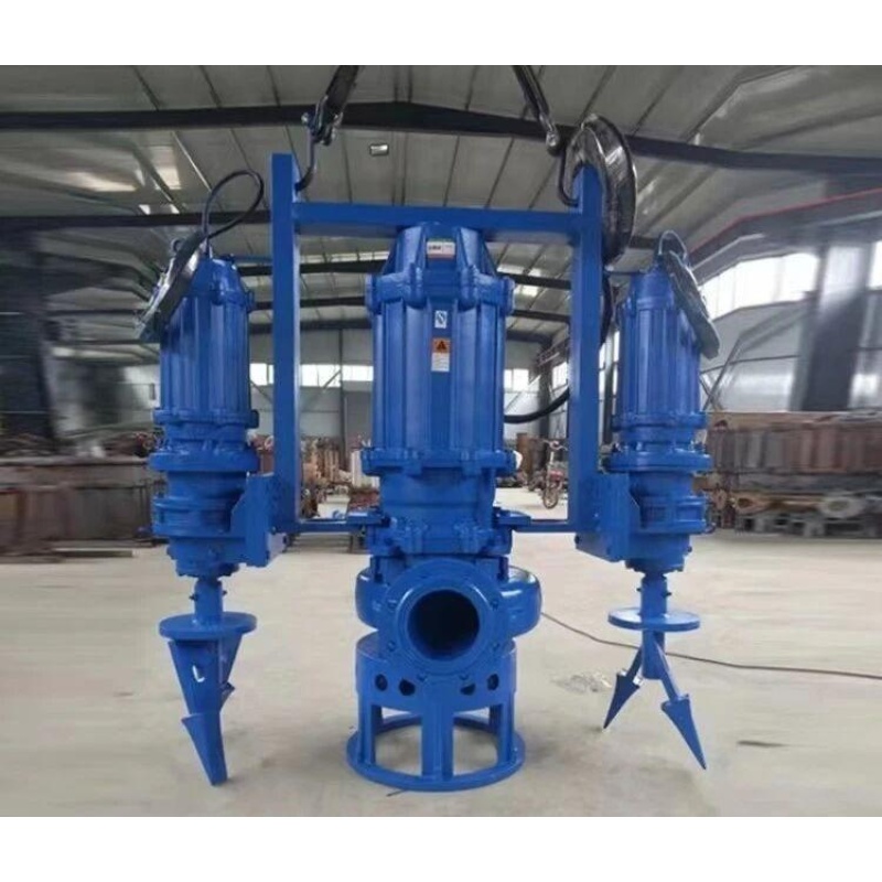
Vertical pumps have their own unique venting requirements. Because the stuffing box is at a high point, extra precautions are required in these cases (typically with Plan 13 venting).
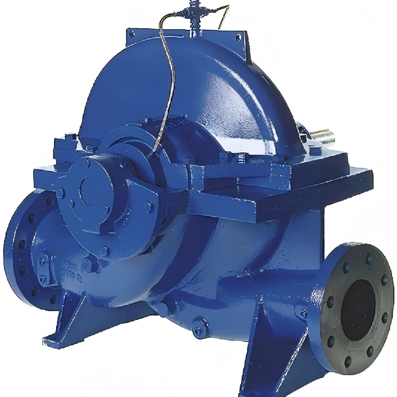
Pumps with centerline discharge piping are generally suitable for automatic venting, but not necessarily for stuffing box or seal chamber venting. Axially split pumps or pumps with tangential discharge will require additional means of venting the pump casing (typically by installing a vent pipe at a high point in the pump casing). Regardless of pump type, air still needs somewhere to go, so make sure it has somewhere to go.
The pump suction inlet is not submerged
When the liquid source is below the impeller centerline, the pump must be vented and primed in some other way. There are three main methods:
1) Use a foot valve (check valve) on the suction side of the pump nozzle. Liquid can be added to the suction line, and the foot valve will hold it in the line until the pump is started.
2) Use an external device to create a vacuum on the suction line. This can be done with a vacuum pump, ejector, or auxiliary pump (usually a positive displacement pump).
3) Use a priming tank or priming chamber.
Additional Tips
Foot valves tend to be unreliable and are notorious for failing or sticking in the worst-case scenario in either the fully open or fully closed position. When it fails in a partial position, you might not realize it's not working.
Any air in the suction line still needs to go somewhere (otherwise it's trapped), and the pump won't be able to compress it. You'll need some type of vent line or automatic vent valve. If there's a check valve downstream, the pump won't be able to generate enough pressure to lift and open the check valve.
Self-priming pumps, or those primed from other sources, require lubrication of the mechanical seal during startup and priming. Many self-priming units address this issue by using an oil-filled seal chamber design. Of course, the pump doesn't necessarily have oil in this chamber; you'll need to add it before startup. Other pumps will require an external lubrication source and/or a separate seal flushing system.
A self-priming pump in operating mode won't leak liquid out of the suction line or seal chamber, as these areas are typically under a certain vacuum, but you do realize that air can leak in.
Other Considerations
The following is a summary of other checks and procedures that are often overlooked when starting a pump, in no particular order.
Safety always comes first and should be the primary guideline. Remember, you may be working with a hot, acid-containing, and automatically starting pressurized system. You are also working next to rotating equipment, which will not hesitate to fight back if the correct operating procedures are not followed.
No matter where you start up equipment, there is a 99% chance that the owner has certain mandatory procedures to follow.
However, the most common oversight I see is the operator's manual being discarded, leading to a long list of incorrect operating habits that include things that should be done on-site but are not. Users must understand that no industrial pump is "plug and play."
A simple check is to crank the pump by hand (also known as "cranking"). The pump should turn freely, without binding or friction. Larger pumps may require additional torque due to inertia, and appropriate tools can be used to overcome this torque (be mindful of how and where you use the tool to prevent damage to the pump shaft).
Cranking should be performed after lubrication or startup, but before seal setting. (If the seal flushing system is active or the seal chamber is filled with flushing fluid and adequately vented, cranking can be performed after seal setting. Three to five cranking turns are typically sufficient.) Furthermore, cranking is much easier before coupling assembly.
This means that the system must be locked out and tagged out (e.g., to prevent accidental startup).
Never power a centrifugal pump without first checking the direction of rotation on the unconnected driver! Incorrect cranking is probably the second most common mistake I see.
New systems often have a significant amount of dirt and debris left in the construction lines. Before starting the pump, it is prudent to install a temporary (commissioning) filter in the suction line. The filter must have sufficient flow area to allow adequate flow without significantly affecting the NPSH margin. The filter must have some method of measuring its own differential pressure; otherwise, you won't know when it's clogged.
Pump systems with long, empty discharge lines will experience problems during initial startup. When the pipeline is full of liquid, the pump has little resistance, so it runs at the "end" (i.e., runout) of the curve. You can introduce temporary artificial resistance by partially closing the outlet valve. The risk of water hammer and related damage also increases when the pipeline system is filled.
Before starting the pump, you should know the expected flow rate and pressure (which will be displayed on the instrument). Also, know the expected ampere readings, frequency (if using a variable frequency drive (VFD)), and power readings in advance. If the facility does not have these devices, I like to bring my own strobe tachometer, vibration probe, and infrared digital thermometer (note: permits are usually required, and many facilities do not allow the use of personal equipment).
Before starting the pump, verify that the mechanical seal support system is working. This is especially important in API seal flushing plans 21, 23, 32, 41, 52, 53, 54, and 62.
For pumps using packing in the stuffing box, check to ensure that a flush line is present and, if so, is it connected to a clean liquid source. Also, check that the stuffing box has sufficient pressure (flow). It's best to start the seal flush before opening the pump's inlet and outlet valves. Consult your pump and/or packing supplier to verify the correct packing leakage rate, which will vary with fluid temperature and other physical properties, shaft speed, and size.
If you can't find a reliable answer for your application, use a standard of 10 drops per minute per inch (per 25 mm) of shaft diameter. During the initial break-in period, I typically choose a more generous leakage rate (30 to 55 drops per minute), regardless of diameter.
Adjust the gland in small increments—adjust each gland nut one equal increment at a time—over several adjustments, taking 15 to 30 minutes to complete. Patience is the key to properly adjusting the packing.
Use all your senses when starting the pump and its auxiliary equipment. Check for sparks, smoke, and friction, such as from improperly set bearing isolators or oil deflectors. Listen for the popping of bubbles in the impeller or the squeal of a mechanical seal desperately in need of lubrication. Can you smell it? The packing shouldn't be smoking. Is the equipment loose due to imbalance or cavitation? Can you feel vibration in the floor and/or piping?
Always minimize the time the pump operates in or near the minimum flow area (left side of the curve). Equally important, avoid operating the pump on the extreme right side of the curve (near the runout point).
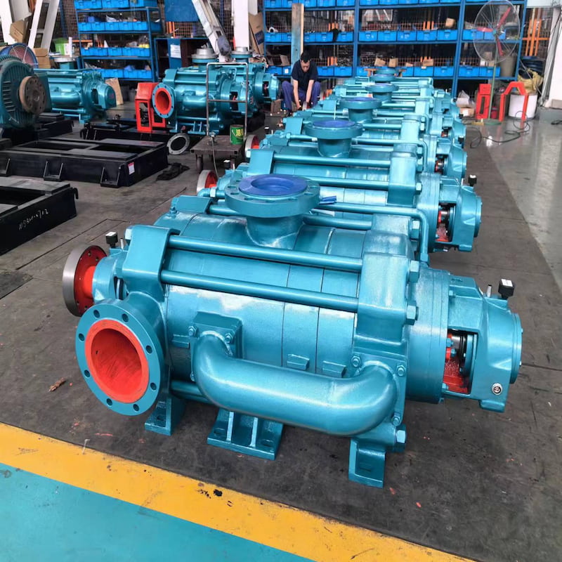
If you are pumping high-temperature media, avoid thermal shock issues by following a warm-up (pump warm-up) procedure before startup. Large pumps may have minimum and maximum allowable temperature rises and cool-down rates. Many multistage pumps will require a warm-up procedure that also involves slow rotation on the cranking gear for a specified time or a predetermined temperature differential.
During startup, closely monitor the bearing metal temperature (or oil temperature). Do not feel the temperature with your hand, as it is not an accurate method. More importantly, most people will feel the bearing housing is hot at 120°F (49°C). Bearing metal or oil temperatures approaching 175°F to 180°F (80°C to 82°C) are not uncommon. The key parameter to observe is the rate of temperature change. A rapid temperature rise is a red flag. When this occurs, it's recommended to shut down the unit and investigate the root cause. The location where the temperature is measured is also important. A platinum RTD inserted into the bearing or on the bearing outer ring provides a more accurate and timely reading than the bearing oil sump or return line temperature.
During commissioning, the motor may be started frequently. Be aware of the number of starts allowed per unit time for your motor. Generally, larger motors with fewer poles have fewer starts allowed.
Pump Outlet Valve Status
I'm often asked: Should the outlet valve be open or closed when the pump starts? My answer is: It depends, but the pump inlet valve should always be open.
Next, let's look at the impeller. There are many things to consider, but the main question we'll answer today is: What is the impeller geometry? Based on this geometry, we'll determine the range of specific speed (Ns), as shown in Figure 1. To understand the concept of specific speed, let's focus on the directional path of the liquid, specifically how it enters and leaves the impeller. Ns is a predictor of the shape of the head, power, and efficiency curves.
Figure 1: Specific Speed Values for Different Impeller Types
Low Specific Speed
If the liquid enters the impeller parallel to the shaft centerline and leaves it at a 90-degree (perpendicular) angle to the shaft centerline, the impeller is in the low specific speed range.
Medium Specific Speed
If the liquid enters the impeller parallel to the shaft centerline and leaves it at a near 45-degree angle, the impeller is in the medium specific speed range. These are mixed flow or Francis blade impellers.
High Specific Speed
If the liquid enters the impeller parallel to the shaft centerline and leaves it parallel to the shaft centerline, this is a high specific speed impeller. This type of axial flow impeller looks similar to a propeller on a ship or aircraft.
Specific Speed vs. Pump Power Curve Shape
Don't know your impeller's specific speed? Ask the equipment manufacturer.
For low specific speed pumps, as you open the pump outlet valve and increase flow, the required brake horsepower (BHP) increases. As you might intuitively expect, this is a direct relationship. For medium specific speed pumps, the BHP curve and its maximum point shift to the left by a nominal amount. In the past, you might not have noticed this change. Axial flow pumps have high specific speeds, and BHP approaches its maximum at lower flow rates, actually decreasing as flow increases. Perhaps contrary to your expectations? Notice that the slope of the power curve changes when the impeller design changes from low to high specific speed.
Read More


 IPv6 network supported.