What are the differences in functions between the feedwater booster pump and the main feedwater pump?
Nov 16, 2026
In boiler feedwater systems, it is common to find the following equipment arrangement: a pre-pump is installed upstream of the main feedwater pump.
Deaerator — Pre-pump — Main feedwater pump — High-pressure heater — Boiler.
When I first encountered the water supply system, I wondered: since the main feed water pump already has the capacity to raise the pressure, why install an additional pump upstream?
This is related to the operating characteristics of the main feed water pump.
The main feedwater pump operates at a high head and high rotational speed, which imposes certain requirements on inlet pressure and the condition of the incoming water. The pre-pump draws water from the deaerator or feedwater tank, first increasing the pressure of the water before delivering it to the inlet of the main feedwater pump.
This is not intended to replace the main feed pump; rather, it provides the main feed pump with stable inlet conditions, thereby reducing issues such as insufficient inlet pressure, flow fluctuations, and cavitation.
I. What is a Pre-pump?
The pre-pump is installed upstream of the main feed water pump, hence the name "pre-pump."
In a boiler feedwater system, the pre-pump draws water from the deaerator or feedwater tank; the water is pressurized and then enters the main feedwater pump, where it undergoes further pressurization before being delivered to the boiler.
The forward pump does not require a high head, but it has a relatively high flow rate; consequently, it has stringent requirements for suction performance.
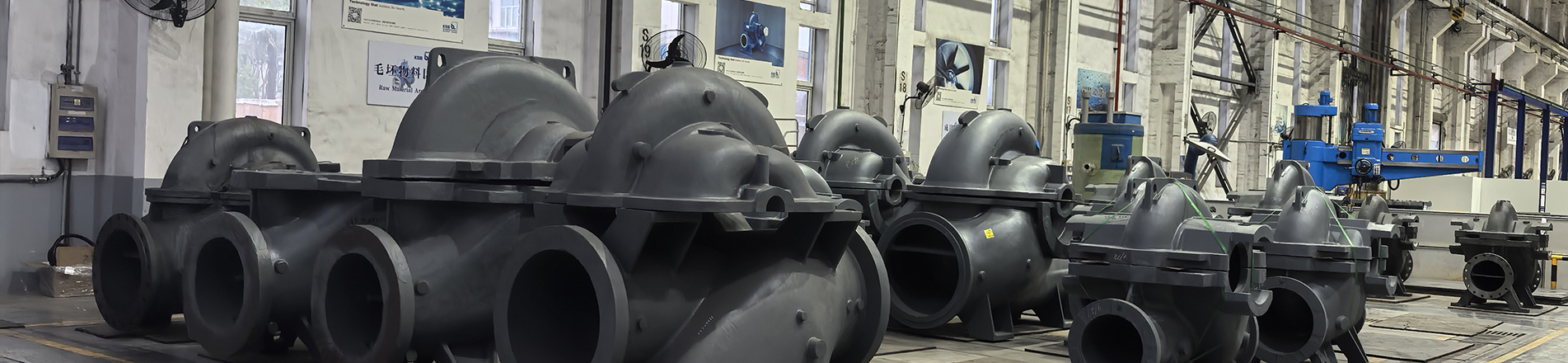
Large-scale units commonly employ horizontal single-stage double-suction centrifugal pumps. Water enters through both sides of the impeller, which reduces the inlet flow velocity, improves the water intake condition, and simultaneously minimizes the axial force caused by pressure imbalance between the two sides of the impeller.
Although the feed pump and the main feed water pump operate in series simultaneously, they have distinct functions:
● The feed pump is responsible for steadily delivering water to the inlet of the main feed water pump;
● The main feedwater pump is responsible for raising the water to the pressure required by the boiler.
II. Why Install a Pre-pump
1. Increase the inlet pressure of the main feed water pump
When the main feed pump is operating, the pressure at the impeller inlet will decrease.
If the inlet pressure is insufficient, the feedwater is prone to localized vaporization after entering the impeller. A pre-pump pressurizes the feedwater first, thereby increasing the inlet pressure of the main feedwater pump and allowing the feedwater to enter the impeller more smoothly.
2. Reduce cavitation in the main feed water pump
Boiler feedwater temperatures are generally relatively high; once local pressure decreases, the water becomes more prone to vaporization. In particular, at the inlet of the main feedwater pump, insufficient pressure can readily cause cavitation, thereby impairing the pump's normal operation.
When the local pressure at the impeller inlet falls below the vapor pressure of the feed water at the current temperature, vapor bubbles form in the water. As these bubbles travel with the flow into regions of higher pressure, they rapidly collapse and repeatedly impact the impeller surface; this phenomenon is known as cavitation.
When cavitation occurs in the pump, the following phenomena often appear at the site:
● There is a crackling sound or a sound resembling the impact of gravel inside the pump;
● The outlet pressure and flow rate exhibit fluctuations;
● Vibration of the pump body and bearings has increased;
● Dull spots or honeycomb-like damage appear on the impeller surface;
● The pump's head and efficiency have decreased.
After the pre-pump raises the inlet pressure of the main pump, the feed water is less likely to vaporize at the impeller inlet, thereby mitigating the impact of cavitation on the main feed-water pump.
3. Stabilize the operating conditions at the main pump inlet
The inlet pressure and flow rate of the main feedwater pump are affected by changes in the deaerator water level, changes in the unit load, and changes in pipeline resistance.
Once the feed pump is put into operation, it can provide continuous and stable water supply to the main feed pump, thereby reducing the direct impact of upstream operating condition variations on the main pump inlet.
4. Assign each pump an appropriate task
If no pre-pump is installed, the main feed water pump must possess both strong water-uptake capacity and the capability to deliver water at high pressure; consequently, both its structural and operational requirements will increase.
After installing the feed pump, the two pumps can be assigned separate tasks:
● The front-end pump features a low head, high-flow-rate design;
● The main feed water pump employs a high-head, multi-stage configuration.
The front-end pump first improves the feedwater conditions, while the main feedwater pump subsequently provides pressure boost; this coordinated operation of the two pumps makes the feedwater process more stable.
III. Structure and Operating Principle of the Pre-pump
Forward-flow pumps generally have a centrifugal-pump configuration and primarily consist of a pump casing, impeller, pump shaft, bearings, shaft seal, coupling, and other components.
1. Pump casing
The interior of the pump casing serves as the flow passage for the feed water and simultaneously withstands the pressure within the pump.
Large forward-flow pumps commonly employ a horizontally split design. During maintenance, the upper pump casing can be disassembled to inspect the impeller, pump shaft, and sealing components without having to remove the inlet and outlet piping.
2. Impeller
The impeller is responsible for transferring mechanical energy to the feed water.
In a double-suction pre-pump, water enters simultaneously from both sides of the impeller. This configuration is particularly suitable for high-flow operating conditions; it also reduces the flow velocity at the inlet, thereby improving the pump's suction conditions.
3. Pump shaft and coupling
The coupling transfers the power from the motor or small steam turbine to the pump shaft, which in turn drives the impeller to rotate.
If the pump shaft is bent, the coupling is misaligned, or there is a significant deviation in the installation position, vibration, bearing overheating, and seal wear are likely to occur during operation.
4. Bearings
Bearings support the rotor, which consists of the pump shaft and impeller, and bear the radial and axial forces generated during operation.
The vibration and temperature of the pump unit are directly affected by the lubrication, cooling, and installation condition of the bearings.
5. Shaft seal
The shaft seal is installed at the point where the pump shaft exits the pump casing; it is used to prevent water supplied inside the pump from leaking outward.
Forward pumps commonly employ mechanical seals and packing seals. Whether the shaft seal operates properly depends on pump shaft vibration, cooling water, flushing water, and installation quality.
6. How does the pre-pump discharge water?
When the pre-pump is operating, the motor or small steam turbine drives the pump shaft through a coupling, causing the impeller to rotate accordingly.
Water enters the impeller at its inlet and, driven by the blades, flows toward the outer periphery of the impeller, thereby acquiring velocity. After leaving the impeller, the water enters the pump casing, where part of its kinetic energy is converted into pressure energy; it then flows from the outlet into the inlet pipeline of the main water supply pump.
The entire process can be understood as follows:
● The feedwater from the deaerator enters the pre-pump; the impeller increases the water pressure, after which the water is delivered to the inlet of the main feedwater pump.
● The front-end pump provides only pressurization for the upstream section; the high pressure required by the boiler is still supplied by the main feedwater pump.
IV. Differences Between the Pre-pump and the Main Feed Water Pump
Comparison Item
Booster pump
Main feed pump
installation site
In front of the main feed pump
Behind the front pump
Assume the task
Improve the inlet conditions for the main pump
Raise the feedwater to the required pressure for the boiler
Head
lower
higher
Traffic characteristics
High traffic volume
Randomized group load variation
Common Structures
Single-stage double-suction centrifugal pump
centrifugal pump of multistage type
Operating Characteristics
Good inhalation performance
Stable inlet pressure is required.
The feed pump is responsible for delivering water to the inlet of the main feed water pump, which then supplies the water to the boiler.
If either of the two pumps is missing, the feedwater system will find it difficult to operate in its original designed condition.
V. How to Reduce Cavitation in the Pre-pump
Front-end pumps are prone to cavitation. When addressing such issues, it is generally necessary to investigate the causes related to inlet water level, pressure, piping, and operating flow rate.
1. Maintain stable water level and pressure in the deaerator
When the deaerator water level drops, the static pressure at the inlet of the pre-pump also decreases.
When the deaerator pressure drops, the feedwater approaches a vaporized state. Therefore, when inspecting the inlet conditions of the pre-pump, the water level, pressure, and water temperature should be evaluated together.
2. Maintain unobstructed inlet piping
Incorrect inlet valve opening, a clogged filter screen, or debris in the pipeline can all increase suction resistance, causing the inlet pressure of the pre-pump to decrease.
Before the pipeline is put into operation after maintenance, the interior of the pipeline and filter screen should also be inspected to prevent welding slag, gasket fragments, and other debris from entering the impeller.
3. Drain all air from the pump body and piping
If air accumulates in the pump housing or inlet piping, the impeller will be unable to draw water properly, causing fluctuations in the pump's outlet pressure and flow rate.
Before startup, the pump must be primed and the system must be vented. Once water continues to flow continuously from the vent and no obvious bubbles are visible, close the vent valve.
4. Avoid prolonged low-flow operation
When the flow rate is too low, a portion of the feed water circulates repeatedly within the pump; as the water temperature gradually rises, the vaporization conditions also change accordingly.
When planning the installation of a recirculation line, the system should first be checked for flowability and for whether the valves operate normally, thereby preventing the pump from operating for extended periods at a flow rate below the allowable level.
VI. Conclusion
The front-end pump is installed upstream of the main feed water pump and is responsible for pressurizing the upstream section and stabilizing the water supply.
Although its head is not particularly high, it directly determines whether the main feed pump can achieve normal inlet pressure and flow rate. In practice, the main feed pump is directly affected by inadequate water intake from the pre-pump, insufficient outlet pressure, or cavitation.
When designing a pre-pump, focus on two key aspects: first, ensure that water is delivered steadily to the inlet of the main feed pump; second, minimize cavitation in the main feed pump caused by insufficient inlet pressure.
Once these two functions are clearly understood, the position and operating principle of the pre-pump within the boiler feedwater system become easier to comprehend.
Read More






 IPv6 network supported.